
Control circuit and control method for power converter with adaptive voltage position control

A power converter and self-adaptive voltage technology, which is applied in the direction of output power conversion devices, control/regulation systems, instruments, etc., can solve the problems of not being able to provide or not being able to provide the variable load line function of multi-phase converters, etc.

Inactive Publication Date: 2011-05-04
RICHTEK TECH
View PDF5 Cites 10 Cited by
  • Summary
  • Abstract
  • Description
  • Claims
  • Application Information

AI Technical Summary

Problems solved by technology

[0011] The control methods of power converters with adaptive voltage position control proposed in the aforementioned documents are all designed with analog controllers. Position control function, but it does not provide a positive load line (Positive Load Line) control function that increases the output voltage when the load current increases
In addition, the load line of the power converter that can be provided is also fixed, and cannot provide the variable load line function required for multi-phase converter operation.

Method used


Image

  • Control circuit and control method for power converter with adaptive voltage position control
  • Control circuit and control method for power converter with adaptive voltage position control
  • Control circuit and control method for power converter with adaptive voltage position control

Examples


Embodiment Construction

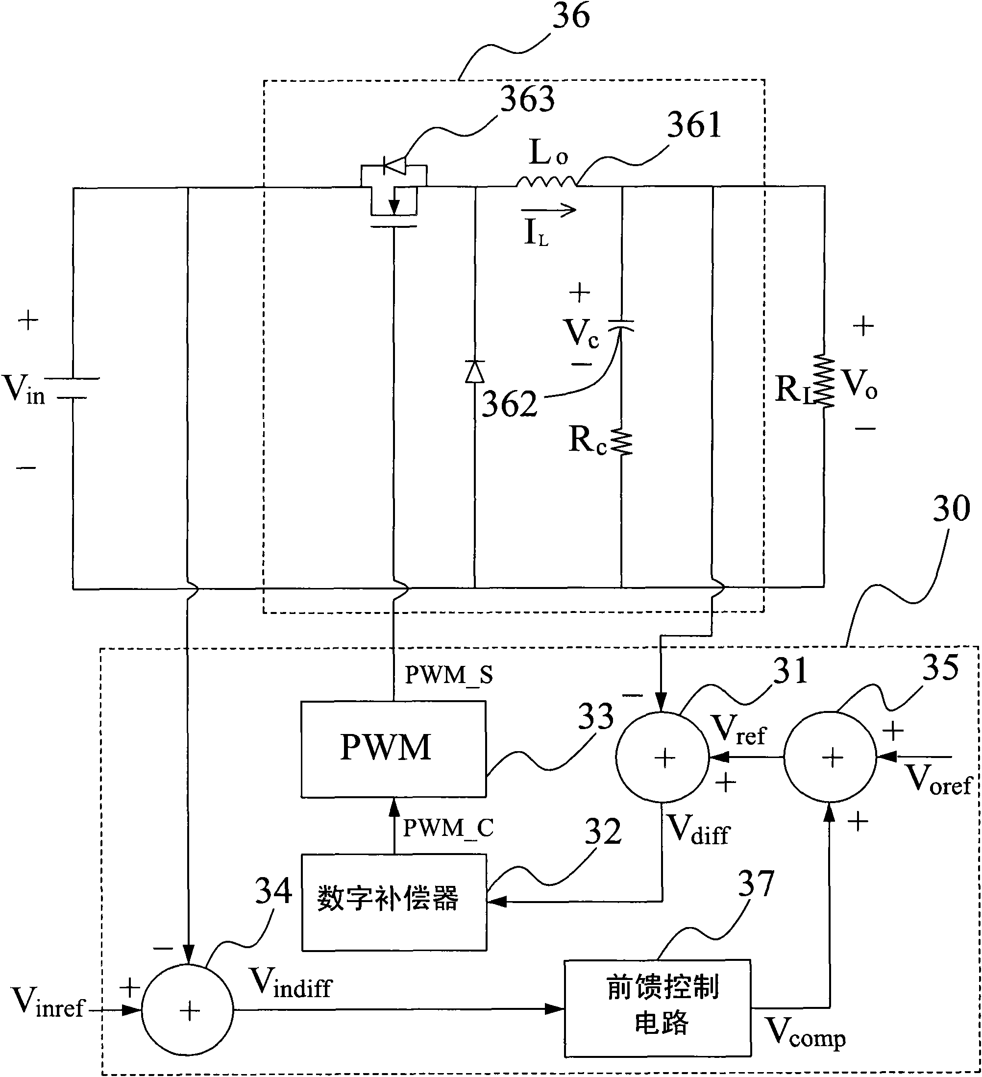
[0027] Please refer to figure 2 As shown, it is a schematic block diagram of a power converter control circuit with adaptive voltage position control according to the first embodiment of the present invention. In the figure, the power converter control circuit 20 includes an adder 21, a digital compensator 22 and a pulse width modulation circuit 23 respectively used to execute the steps of the power converter control method, which can be used to generate a pulse width modulation signal PWM_S to control The power switch 263 of the power converter 26 is turned on and off.

[0028] Wherein, the adder 21 is used to receive the output voltage V of the power converter 26 O with the output reference voltage V ref , and obtain the output voltage V O with the output reference voltage V ref The output voltage difference between V diff . The digital compensator 22 has a Z conversion transfer function for referring to the output voltage difference V of the adder 21 output diffto g...


PUM


Abstract

The invention provides a control circuit and control method for a power converter with adaptive voltage position control. The control method comprises the following steps: acquiring an output voltage difference between an output voltage and an output reference voltage by using a summator; referring to the output voltage difference by using a digital compensator with a Z-transform transfer function so as to generate a pulse width control signal, adjusting least significant bit (LSB) of the denominator coefficient of the Z-transform transfer function to realize the load line controlling function of the power converter; and controlling the pulse width modulation circuit by using the pulse width control signal to generate a pulse width modulation signal for controlling power-on / off of the power of the power converter. Therefore, the control function of a negative load line or a positive load line, and a variable load line controlling function required by a multi-phase converter can be easily realized without complicated operation.

Description

technical field [0001] The present invention relates to a power converter, and in particular to a power converter control circuit with adaptive voltage position (Adaptive Voltage Position, AVP for short) control and a control method thereof. Background technique [0002] With the rapid evolution of semiconductor technology, such as computers and their peripheral digital products are also being updated day by day. In the integrated circuit (IC for short) of the computer and its peripheral digital products, due to the rapid change of the semiconductor process, there are more diversified demands for the power supply of the integrated circuit, so that the application such as booster (Boost Converter), step-down PWM regulators combined with various power converters such as buck converters to meet the different power requirements of various integrated circuits have also become one of the most important factors for the ability to provide diversified digital products . [0003] In...

Claims


Application Information

Patent Timeline
IPC IPC(8): H02M3/157
Inventor 林育政陈德玉张炜旭
Owner RICHTEK TECH
Learn More