Flexible coupling

A flexible coupling and coupling body technology, applied in the field of mechanical parts, can solve the problems of coupling noise and vibration, and achieve the effect of low noise and vibration

Inactive Publication Date: 2011-05-04
WUXI NO 2 BEARING
View PDF5 Cites 8 Cited by
  • Summary
  • Abstract
  • Description
  • Claims
  • Application Information

AI Technical Summary

Problems solved by technology

[0003] The purpose of the present invention is to overcome the deficiencies in the prior art, provide a flexible coupling that can realize the flexible connection between the input shaft and the output shaft, and solve the noise and vibration problems of the coupling

Method used


Image

  • Flexible coupling
  • Flexible coupling

Examples


Embodiment Construction

[0010] The present invention will be further described below in conjunction with specific drawings and embodiments.

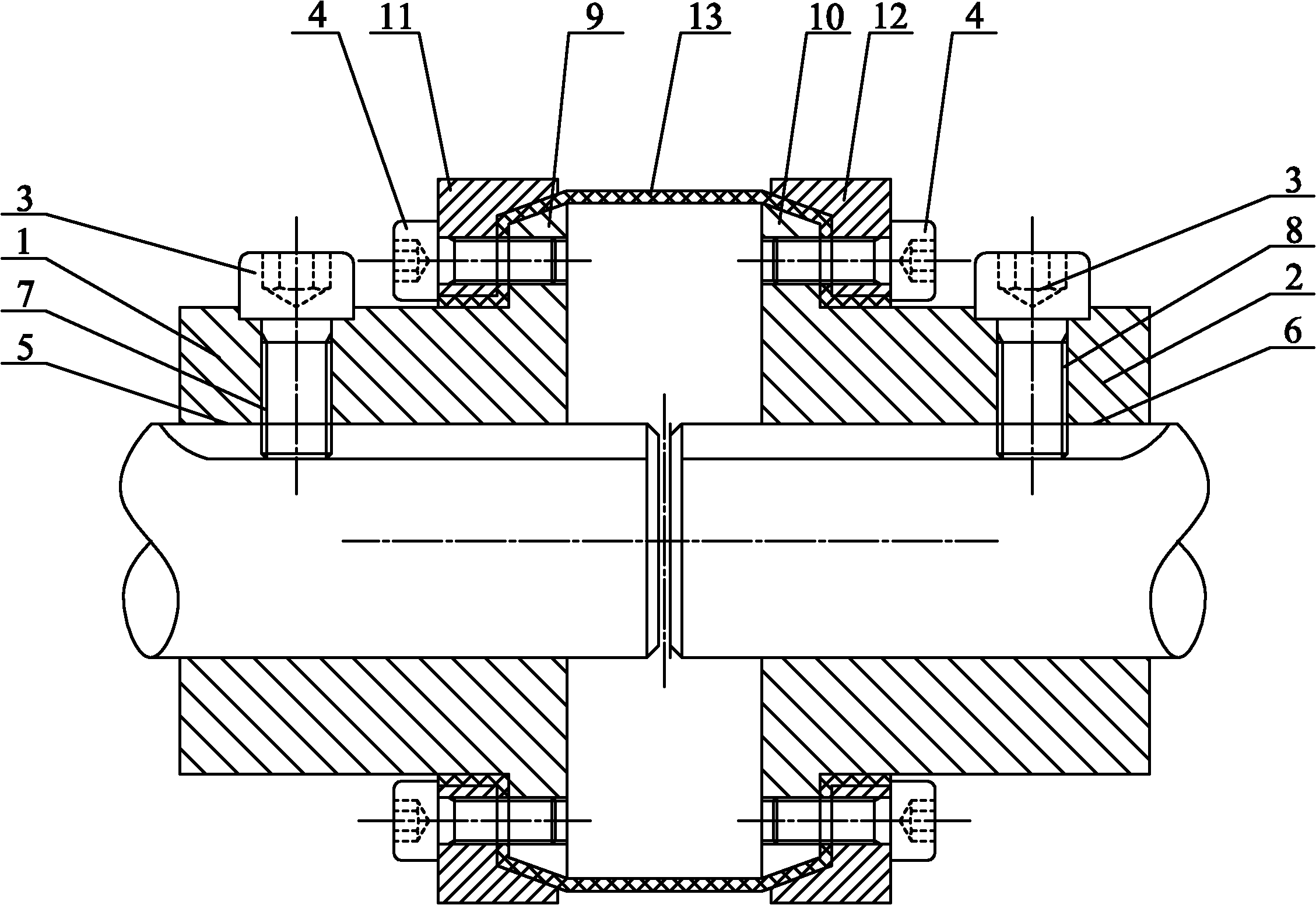
[0011] As shown in the figure, the flexible coupling includes a left coupling body 1, a right coupling body 2 and a set screw 3, and an input shaft hole 5 and a left set screw hole 7 are opened on the left coupling body 1 , the inner end of the left set screw hole 7 communicates with the input shaft hole 5, the left set screw hole 7 cooperates with the set screw 3, and the left mounting rib 9 is integrally connected to the right end of the outer wall of the left coupling body 1; The right coupling body 2 is provided with an output shaft hole 6 and a right set screw hole 8, the inner end of the right set screw hole 8 communicates with the output shaft hole 6, and the right set screw hole 8 cooperates with the set screw 3 , a right mounting rib 10 is integrally connected to the left end of the outer wall of the right coupling body 2; the input shaft hole 5 and th...


PUM


Abstract

The invention relates to a flexible coupling, which comprises a left coupling body, a right coupling body and a fastening screw, wherein the left coupling body is provided with an input shaft hole and a left fastening screw hole; the inner end part of the left fastening screw hole is communicated with the input shaft hole; the right end part of the outer wall of the left coupling body is provided with a left installation fin; the right coupling body is provided with an output shaft hole and a right fastening screw hole; the inner end part of the right fastening screw hole is communicated with the output shaft hole; the left end part of the outer wall of the right coupling body is provided with a right installation fin; a left pressing sleeve and the left installation fin are provided with left compression screw holes; a right pressing sleeve and the right installation fin are provided with right compression screw holes; the left end part of flexible transmission cloth is tightly pressed and arranged between the left pressing sleeve and the left installation fin; and the right end part of the flexible transmission cloth is tightly pressed and arranged between the right pressing sleeve and the right installation fin. Flexible connection of an input shaft with an output shaft is realized and noise and vibration are small.

Description

technical field [0001] The invention relates to a mechanical part, in particular to a flexible shaft coupling. Background technique [0002] The coupling is one of the commonly used mechanical parts in the transmission system of the machinery industry. Its main function is to transmit the power of the input shaft to the output shaft between two shafts that are not completely concentric. Due to the non-concentricity of the two shafts, the power of the input shaft can be smoothly transferred to the output shaft only through the coupling. A common shaft coupling has two coupling bodies, and there are four connecting holes on the coupling body. Nylon sleeves are placed in the holes, and four pins are used to pass through the nylon sleeves. Such a coupling can realize the transmission function, but there are problems in that the noise is large and the vibration generated is relatively large. Nowadays, more stable and low-noise couplings are required in many occasions, such as b...

Claims


Application Information

Patent Timeline
IPC IPC(8): F16D3/56
Inventor 谭义银
Owner WUXI NO 2 BEARING
Why Eureka
Try Eureka