
Microsphere logging instrument sidewall contact device

A logging tool and pusher technology, which is used in surveying, wellbore/well components, and earth-moving drilling and mining, etc., can solve the problems that the microsphere and microsphere cannot be detected at the head, the electrode plate cannot be close to the well wall, and the opening and so on. , to achieve the effect of ensuring full utilization

Inactive Publication Date: 2011-05-04
SHENYANG XINJIN GASOLINEEUM EQUIP
View PDF4 Cites 10 Cited by
  • Summary
  • Abstract
  • Description
  • Claims
  • Application Information

AI Technical Summary

Problems solved by technology

However, during the logging process, the axial direction of the instrument is random, and the pusher arms on both sides of the end of the pusher cannot be opened to different extents according to the specific conditions of the borehole diameter, causing the polar plate to sometimes not be close to the borehole wall, such as Figure 5 As shown, the signal is interrupted, which also corresponds to a common saying in oilfield microsphere logging: "Microsphere microspheres can never be measured to the end."
This is extremely unfavorable for well logging sites with changing drilling conditions, and seriously affects the accuracy of detection results

Method used


Image

  • Microsphere logging instrument sidewall contact device
  • Microsphere logging instrument sidewall contact device
  • Microsphere logging instrument sidewall contact device

Examples


Embodiment Construction

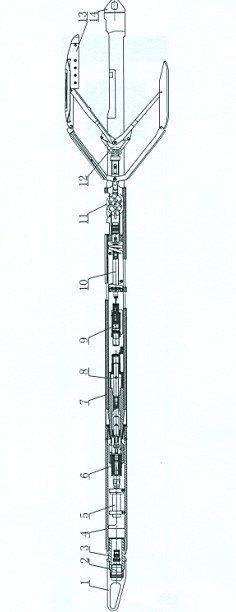
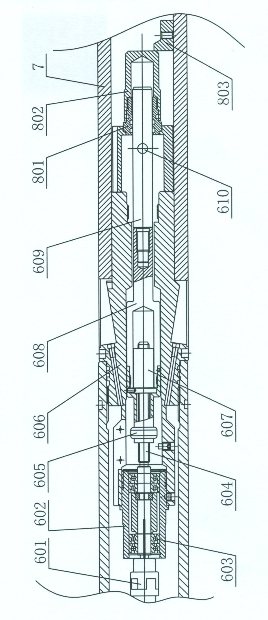
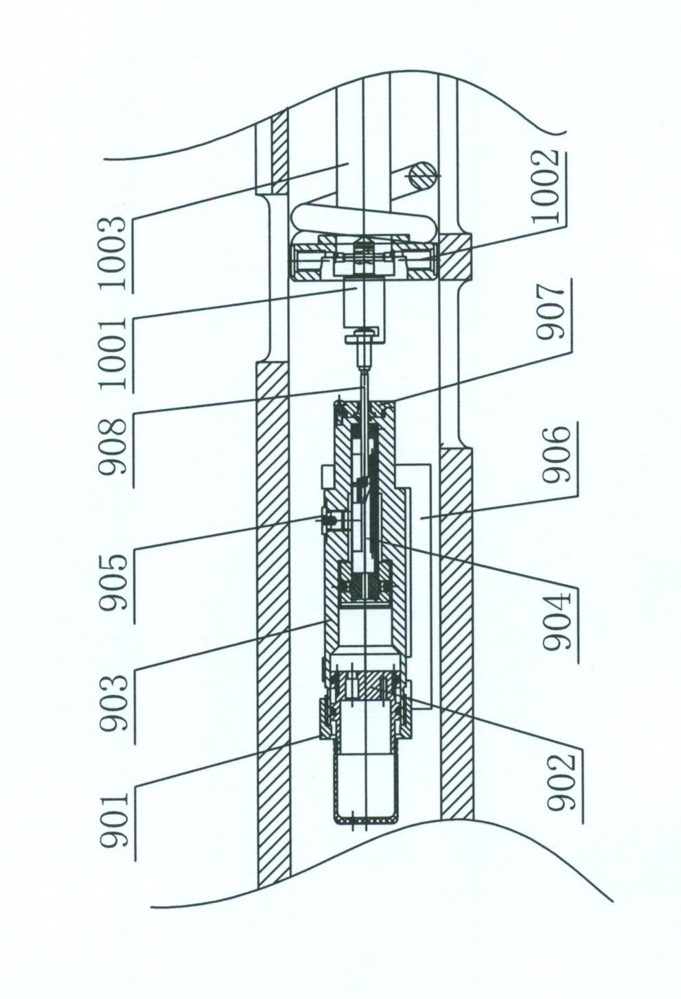
[0021] according to Figure 1-6 The present invention is described in detail. The invention belongs to the main component of the polar plate type current focusing logging instrument, and provides a reliable mechanical pushing guarantee for the microsphere logging instrument that simultaneously measures the resistivity Rx0 and the two curves of the borehole diameter of the underlying flushing zone, and has autonomy. Innovative products.

[0022] Such as figure 1 As shown, the present invention is mainly composed of a housing, a motor assembled in the housing in turn, a transmission assembly, a pressure balance assembly, a borehole potentiometer assembly, a spring assembly, a hinge assembly, and a pusher connected to the hinge assembly. Terminals, protective caps at both ends of the shell, lower plugs, etc. Wherein, the shell is an upper shell and a lower shell, and the upper shell and the lower shell are connected by an intermediate joint. An upper joint 3 is connected bet...


PUM


Abstract

The invention discloses a microsphere logging instrument sidewall contact device, which solves the problems that a logging instrument sidewall contact device used in a conventional oil field limits the detection and influences a detection result of an irregular detected well wall fundamentally. The microsphere logging instrument sidewall contact device comprises a shell, a motor, a drive assembly, a pressure balance assembly, a borehole diameter potentiometer assembly, a spring assembly, a hinge assembly and a pushing end, wherein the motor, the drive assembly, the pressure balance assembly, the borehole diameter potentiometer assembly, the spring assembly and the hinge assembly are arranged in the shell in turn; and the pushing end is connected with the hinge assembly. The technical points of the microsphere logging instrument sidewall contact device are that: the hinge assembly comprises a connecting frame and a hinge connecting rod group connected with the spring assembly; the hinge rod group is a dual-hinge four-connecting-rod mechanism for realizing reverse movement; the front hinge four-connecting-rod mechanism and the back hinge four-connecting-rod mechanism of the dual-hinge four-connecting-rod mechanism use two intermediate connecting rods commonly and are fixed with the shell at a hinge position of the two intermediate connecting rods; the front end of the front hinge four-connecting-rod mechanism is connected with the connecting frame; and the back end of the back hinge four-connecting-rod mechanism is connected with the pushing end. The microsphere logging instrument sidewall contact device changes a linkage working mode of the conventional sidewall contact device, and realizes a working state of the sidewall contact device by fully utilizing a spring tension of the spring assembly.

Description

technical field [0001] The invention relates to the technical field of oil field logging, in particular to a widely applicable microsphere logging tool pusher. Background technique [0002] The logging tool is suitable for the field of well logging, and can continuously scan the borehole wall, and can also scan any horizontal horizontally, and provide technical data such as the vertical section of the wellbore, the horizontal section, the effective section of the wellbore, and the deviation distance of the wellbore. The logging results can be directly displayed on the computer screen or given by the plotter printer, which is flexible and convenient to use. The use of logging instruments can prevent wellbore deviation, reduce construction period, speed up construction progress, ensure project quality, and have obvious indirect economic benefits and very significant social benefits. [0003] Due to the difference in geological conditions and drilling techniques, after the dri...

Claims


Application Information

Patent Timeline
IPC IPC(8): E21B47/08E21B49/00
Inventor 于其蛟王绍山
Owner SHENYANG XINJIN GASOLINEEUM EQUIP
Learn More