
Controller for automatic transmission

A technology for automatic transmissions and control devices, applied in the direction of transmission control, elements with teeth, belts/chains/gears, etc., can solve damage to operational flexibility, reduce fuel consumption and operational flexibility, lack of realizability And other issues

Inactive Publication Date: 2011-04-27
AISIN AW CO LTD
View PDF1 Cites 12 Cited by
  • Summary
  • Abstract
  • Description
  • Claims
  • Application Information

AI Technical Summary

Problems solved by technology

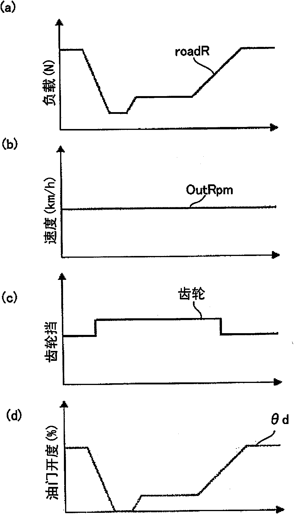
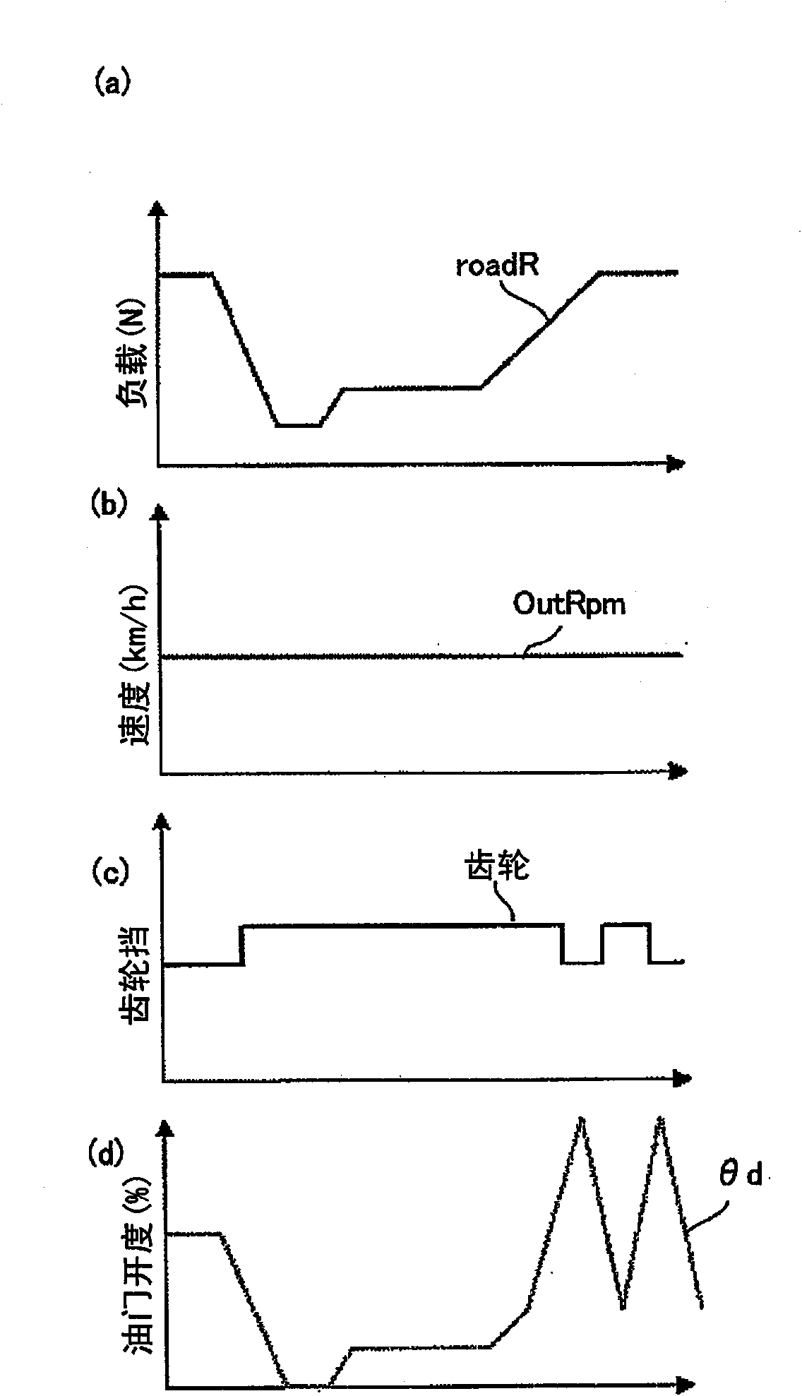
However, changing the engine speed to a high speed gear with the engine speed controlled at a lower speed side has the following problems. Changing gears to drive, resulting in an increase in the frequency of immediate downshifts, that is, prone to busy shifts with frequent repeated shifts, which tends to impair drivability
[0004] In order to solve the problem of achieving reduced fuel consumption and operational flexibility, it is considered to prepare, for example, a plurality of shift tables of more than one hundred kinds by further subdividing the above-mentioned shift tables, so as to adjust the speed change table according to the situation (running resistance and driving style) at the time. Etc.) to select the optimal shift gear by switching multiple shift tables at the right time to optimize the shift judgment. However, when considering the preparation of so many shift tables and the switching control of the shift tables, there is a lack of realizability

Method used


Image

  • Controller for automatic transmission
  • Controller for automatic transmission
  • Controller for automatic transmission

Examples


no. 2 approach

[0171] Next, follow Figure 26 and Figure 27 , and a second embodiment in which the above-mentioned first embodiment is partially modified will be described. In this second embodiment, compared with the first embodiment described above, the values ​​in the downshift determination and the upshift determination determined by the downshift determination means 51 and the upshift determination means 52 are changed.

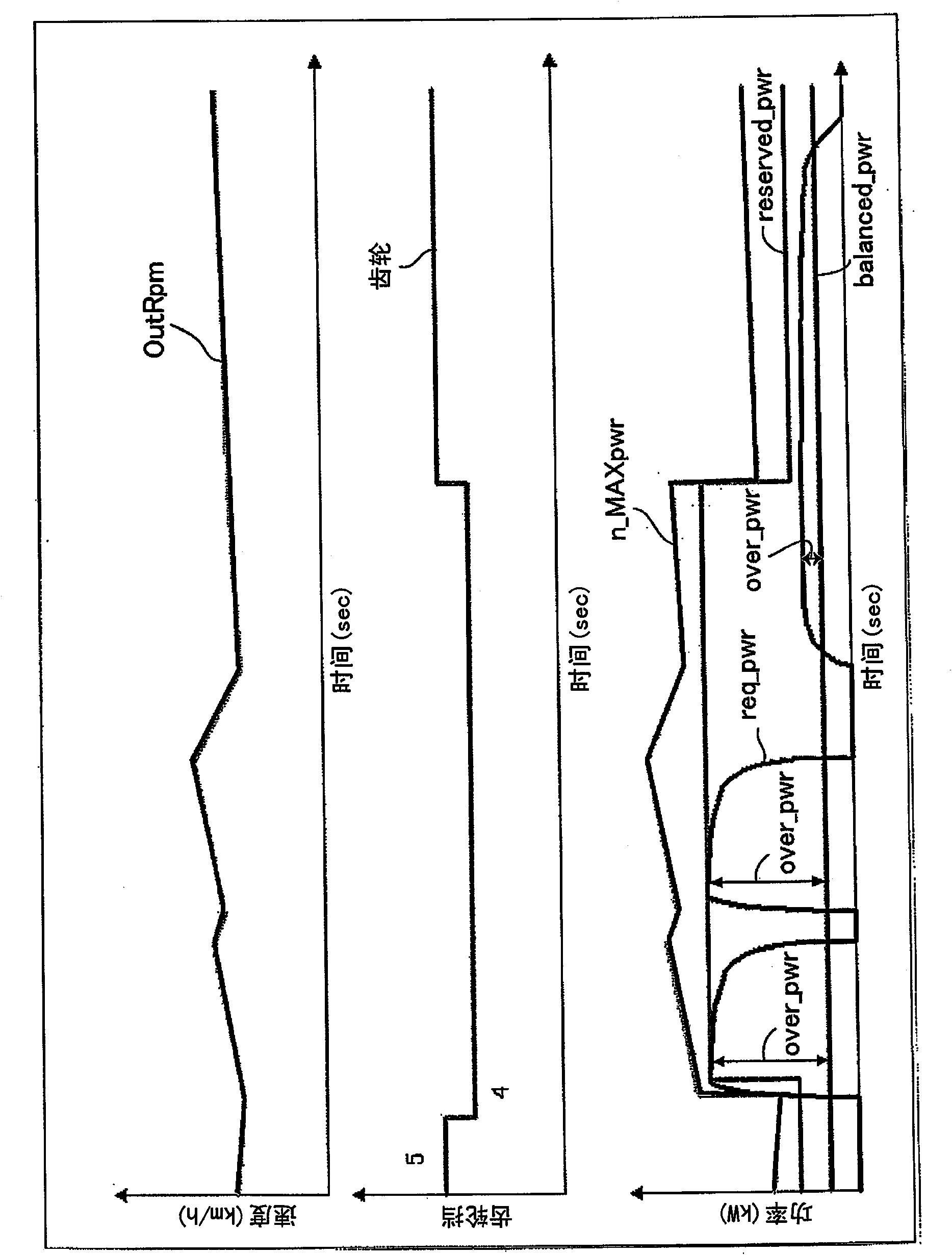
[0172] That is, in the above-mentioned first embodiment, the current gear ratio maximum power n_MAXpwr is used as a reference when determining a downshift, and the maximum power after upshifting n+_MAXpwr is used as a reference when determining an upshift. However, in the second embodiment In the mode, a value obtained by subtracting the surplus power E / G_reserved_pwr (drive source surplus output) capable of accelerating the rotation of the engine 2 is used from the above-mentioned value.

[0173]Therefore, in the downshift judgment of the second embodiment, the val...

no. 3 approach

[0191] Next, follow Figure 28 and Figure 29 , and a third embodiment in which the above-mentioned second embodiment is partially modified will be described. Compared with the second embodiment described above, this third embodiment further changes the values ​​in the downshift determination and upshift determination determined by the downshift determination unit 51 and the upshift determination unit 52 .

[0192] That is, in the above-mentioned second embodiment, the larger value of the value obtained by adding the balance power balanced_pwr to the remaining output reserved_pwr and the requested power req_pwr is used as the first value when making a downshift judgment, and when making an upshift judgment, set The value obtained by adding the balanced power balanced_pwr to the remaining output reserved_pwr, the value obtained by adding the larger one of the required power req_pwr plus the hysteresis power hys_pwr is used as the third value, and in this third embodiment, the ...

no. 4 approach

[0211] Next, follow Figure 30 and Figure 31 A fourth embodiment partially modified from the first embodiment described above will be described. In this fourth embodiment, the calculation method of the remaining output reserved_pwr is changed compared to the first embodiment described above.

[0212] The remaining output calculation unit 31' of the fourth embodiment switches between the normal (Normal) mode, the economical (ECO) mode, and the sport (Sport) mode based on the required excess amount over_pwr obtained by subtracting the balanced power balanced_pwr from the required power req_pwr and the accelerator opening θd. For these three modes, a value corresponding to each mode is used as the remaining output reserved_pwr.

[0213] In detail, for example, during running in the normal mode, when the remaining output calculation unit 31' judges (five times) that the accelerator pedal is depressed and the required excess amount over_pwr is below the first threshold a1 (eg, 1...


PUM


Abstract

A sustaining output calculation means (33) calculates a sustaining output needed for sustaining a vehicular velocity based on a travel resistance, and a requested output calculation means (32) calculates a requested output based on an accelerator opening, for example. Meanwhile, a maximum output calculation means (40) calculates the current gear ratio maximum output as the maximum output of the vehicle at the current gear ratio based on the maximum output characteristic of an engine (2), and a post-upshift maximum output as the maximum output of the vehicle at the gear ratio after the gear is upshifted. Then, downshifting is determined when a first value calculated based on the sustaining output, the requested output, and the excess output has become greater than a second value calculated based on the current gear ratio maximum output, and upshifting is determined when a third value calculated based on the sustaining output, the requested output, and the excess output has become smaller than a fourth value calculated based on the post-upshift maximum output. Selection of the gear ratio based on aforementioned calculations is enabled in order to facilitate further improvement of the fuel efficiency.

Description

technical field [0001] The present invention relates to a control device for an automatic transmission mounted on a vehicle, and more specifically, to a control device for an automatic transmission that selects a gear ratio of a transmission mechanism by calculation. Background technique [0002] Generally, in a multi-speed automatic transmission mounted on a vehicle, a shift table is preset (prepared) at the time of manufacture, and a shift speed is selected (judged) while driving based on the vehicle speed and accelerator opening with reference to the shift table. In addition, various types of tables are prepared in advance, such as tables according to driving resistance such as flat road, uphill road, and downhill road, and tables according to driving types such as sports, normal, and economical, etc., in order to make a good shift judgment. [0003] However, in recent years, vehicles have been further required to reduce fuel consumption in consideration of environmental ...

Claims


Application Information

Patent Timeline
Patent Type & Authority Applications(China)
IPC IPC(8): F16H61/02F16H59/18F16H59/44F16H61/686F16H61/68F16H61/684F16H63/50
CPCF16H61/0213
Inventor 浅井雅广草部圭一朗
Owner AISIN AW CO LTD
Learn More