
An energy recovery system for a vehicle driveline

A kinetic energy recovery system and transmission system technology, applied in the field of kinetic energy recovery systems, can solve problems such as small expected range

Inactive Publication Date: 2011-04-27
TOROTRAK (DEV) LTD
View PDF7 Cites 3 Cited by
  • Summary
  • Abstract
  • Description
  • Claims
  • Application Information

AI Technical Summary

Problems solved by technology

[0005] When using a conventional transmission in a KERS system, the problem arises that the range of gear ratios provided by a typical transmission will be smaller than the desired range of speed ratios between the engine and flywheel

Method used


Image

  • An energy recovery system for a vehicle driveline
  • An energy recovery system for a vehicle driveline
  • An energy recovery system for a vehicle driveline

Examples


Embodiment Construction

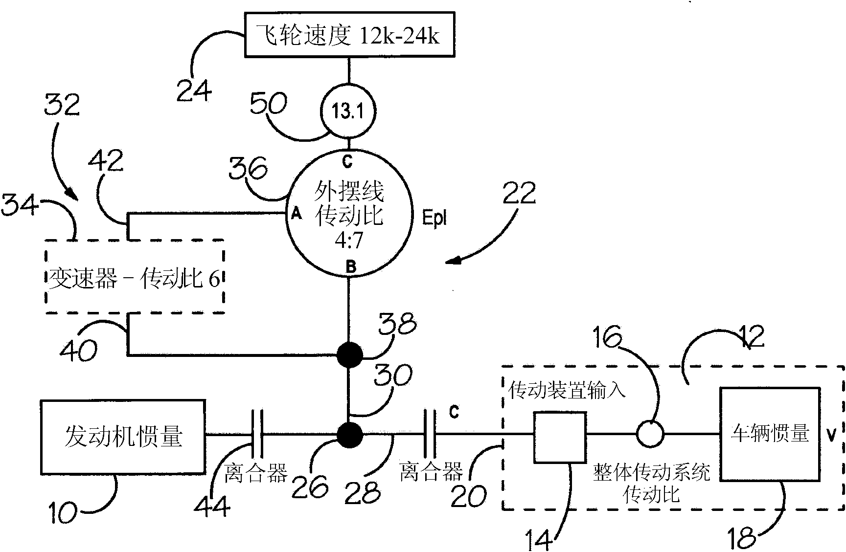
[0019] figure 1 The engine 10 shown is in the present embodiment an internal combustion engine, although in principle the invention could be implemented using another type of rotary drive. The drivetrain shown is intended for use in a motor vehicle, but can also be applied to other types of vehicles, such as trains. figure 1 The dashed box 12 in contains what is representative of any motor vehicle driveline. In the figure, the transmission of the vehicle, which is used to transmit rotational drive from the engine 10 to the driven wheels of the vehicle, is represented by box 14 (which is the transmission input) and circle 16 (which represents the speed ratio of the transmission) (not shown). The transmission may be of any suitable type and may provide stepped or continuously variable gear ratios. The driving force transmitted to the wheels acts on the vehicle inertia 18 to accelerate / decelerate it. In this example, the first clutch 20 is used to selectively disengage the tr...


PUM


Abstract

The invention concerns a kinetic energy recovery system for use in a vehicle driveline. The system has a flywheel (24) serving to store energy. A continuously variable transmission (32) serves to transfer drive between the flywheel and a driveline of the vehicle at a steplessly variable CVT speed ratio. The continuously variable transmission has a variator (34) which has a rotary variator input (40) and a rotary variator output (42). The variator serves to transfer drive between its input and output at a continuously variable variator speed ratio. The continuously variable transmission further comprises a shunt gear arrangement (36) having a first rotary shunt input which is drivably coupled to the rotary variator input, a second rotary shunt input which is drivably coupled to the rotary variator output, and a shunt rotary output which is drivably coupled to the flywheel.

Description

technical field [0001] The present invention relates to a kinetic energy recovery system for a vehicle. Background technique [0002] Hybrid powertrains are generally seen as a fundamental solution in the road transport sector, where the kinetic energy traditionally wasted via braking is recovered and reused, with the goal of reducing fuel consumption and emissions. Hybrid powertrains may also be applied to other vehicles, especially trains. Most hybrid systems in production and in development are based on electrical structures with a variety of designs and storage media. However, converting mechanical energy into electrical energy and then into chemical energy (and vice versa) results in considerably lower system efficiencies. Additionally, storage media, power electronics, and motor / generators create complex powertrains with corresponding impacts on system cost, weight, and packaging. [0003] An alternative to an electric hybrid powertrain is a mechanical hybrid system...

Claims


Application Information

Patent Timeline
IPC IPC(8): B60K6/10F16H37/08
CPCB60K6/105Y02T10/6204F16H37/0853Y02T10/62Y10T74/19051
Inventor 克里斯托弗·约翰·格林伍德
Owner TOROTRAK (DEV) LTD
Learn More