
Multi-camera system calibrating method based on optical imaging test head and visual graph structure

An optical imaging, multi-camera technology, applied in the field of visual measurement, can solve the problems of initial parameter error, low efficiency, low precision, etc.

Active Publication Date: 2011-04-27
SUZHOU DEKA TESTING TECH CO LTD
View PDF5 Cites 56 Cited by
  • Summary
  • Abstract
  • Description
  • Claims
  • Application Information

AI Technical Summary

Problems solved by technology

However, in the traditional multi-camera calibration methods, some use electronic theodolite to establish the world coordinate system, which increases the cost and complexity of the system; some use three-dimensional, two-dimensional, one-dimensional or 0-dimensional calibration objects, directly using the internal The parameters and the pose relationship between the cameras complete the estimation of the calibration parameters of the multi-camera system. On the one hand, the calibration object is required to be visible in the field of view of all cameras. On the other hand, the calibration results will be affected by noise, calculation errors, and initial parameter errors. Low; although some methods also use the bundle adjustment optimization method in the final stage of calibration, the acquisition process of the 3D calibration point set is more complicated, and the outlier points need to be discarded, the efficiency is low, and the robustness is poor

Method used


Image

  • Multi-camera system calibrating method based on optical imaging test head and visual graph structure
  • Multi-camera system calibrating method based on optical imaging test head and visual graph structure
  • Multi-camera system calibrating method based on optical imaging test head and visual graph structure

Examples


Embodiment Construction

[0069] The present invention will be further described below in conjunction with accompanying drawing.

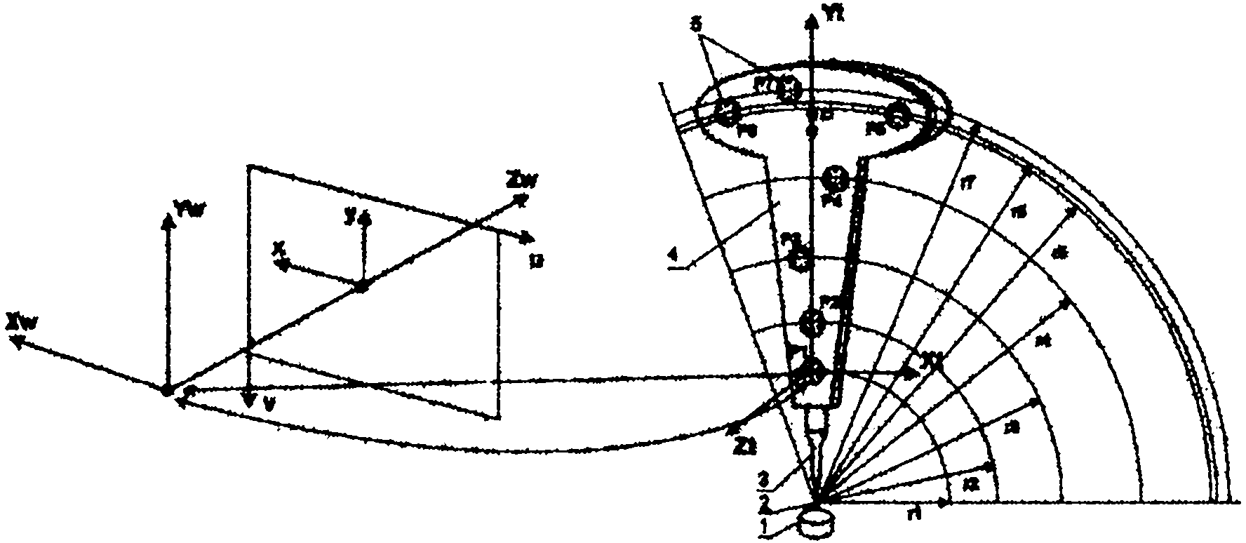
[0070] Take the vision system composed of 8 cameras as an example for specific description. The present invention uses as figure 1 Optical imaging probe shown. The optical imaging probe is mainly composed of a measuring tip (2), an extension rod (3), a target body (4), 7 mark points (5) and LED light spots thereof. The distribution of 8 cameras is as follows image 3 As shown, all cameras are not required to have overlapping fields of view, but at least every two cameras have overlapping fields of view. According to the spatial distribution of 8 cameras, the method first selects and determines the spatial positioning points, and uses the rotation invariant relationship of the optical imaging probe around the measuring tip to complete the independent calibration of a single camera and the relative pose calibration of every two cameras. Then, the multi-camera connection r...


PUM


Abstract

The invention provides a multi-camera system calibrating method based on an optical imaging test head and a visual graph structure. The method comprises the following steps: independently calibrating each camera by the optical imaging test head to obtain the initial values of the internal parameter and aberration parameter of each camera; calibrating the multiple cameras two by two, and obtaining the fundamental matrix, polar constraint, rotation matrix and translation vector between every two cameras with a plurality of overlapped regions at a view field by means of linear estimation; building the connection relationship among the multiple cameras according to the graph theory and the visual graph structure, and estimating the rotation vector quantity initial value and translation vector quantity initial value of each camera relative to the referred cameras by a shortest path method; and optimally estimating all the internal parameters and external parameters of the all cameras and the acquired three-dimensional sign point set of the optical imaging test head by a sparse bundling and adjusting algorithm to obtain a high-precision calibrating result. The multi-camera system calibrating method is simple in a calibrating process from the partial situation to the overall situation and from the robust to the precise, ensures high-precise and robust calibration, and is applied to calibrating multi-camera systems with different measurement ranges and different distribution structures.

Description

technical field [0001] The invention belongs to the technical field of visual measurement, and relates to a multi-camera system calibration method based on an optical imaging probe and a visual map structure. Background technique [0002] Using a multi-camera system for 3D measurement must first complete the internal parameters and distortion parameters of each camera, the relative pose between the multi-cameras and the calibration of the pose parameters with the reference coordinate system. The robustness and accuracy of the calibration directly determine the measurement accuracy of the multi-camera system, so robust and high-precision calibration is the prerequisite and condition for the multi-camera system to achieve high-precision calibration. [0003] Camera calibration has a long history, and after decades of development, there are many effective methods. In recent years, multi-camera systems have attracted extensive attention both at home and abroad due to their uniq...

Claims


Application Information

Patent Timeline
IPC IPC(8): G06T7/00G03B35/08
Inventor 赵宏李进军
Owner SUZHOU DEKA TESTING TECH CO LTD
Learn More