
Diagnostic strategy for a fuel vapor control system

A fuel vapor and control system technology, applied to the charging system, adding non-fuel substances to fuel, engine components, etc., can solve problems such as wear and tear, reduced vehicle efficiency, and inability to diagnose components

Inactive Publication Date: 2011-04-27
FORD GLOBAL TECH LLC
View PDF5 Cites 8 Cited by
  • Summary
  • Abstract
  • Description
  • Claims
  • Application Information

AI Technical Summary

Problems solved by technology

For example, spinning the engine to perform diagnostic tests reduces the vehicle's operating efficiency and causes unnecessary wear and tear between various engine components such as the electric motor used to spin the engine and the cylinder valves
Also, the diagnostic tests described above determine the integrity of the entire fuel vapor control system without diagnosing individual components

Method used


Image

  • Diagnostic strategy for a fuel vapor control system
  • Diagnostic strategy for a fuel vapor control system
  • Diagnostic strategy for a fuel vapor control system

Examples


Embodiment Construction

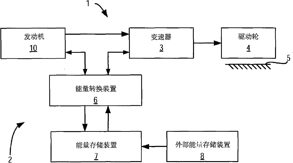
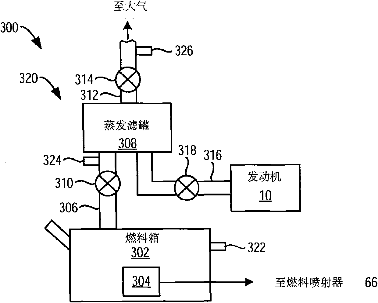
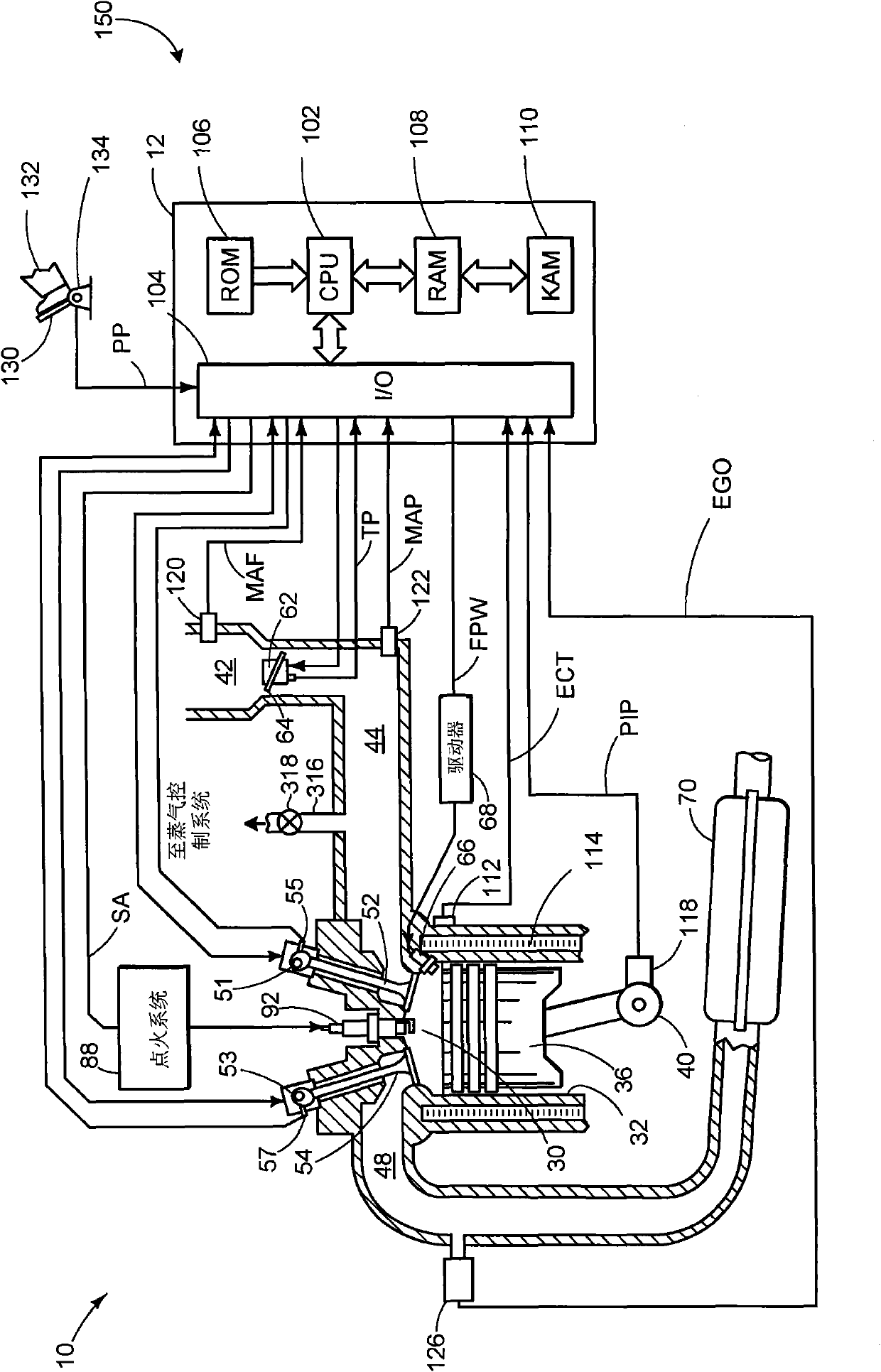
[0022] figure 1 A schematic depiction of a vehicle with a hybrid drive system is illustrated, figure 2 A schematic depiction of an internal combustion engine that may be included in the hybrid drive system is illustrated. image 3 Indicates that can be included in figure 1 A schematic depiction of the fuel vapor control system within the vehicle shown in , and Figure 4 A method for operating a fuel vapor control system is shown. In one example, a method for operating a fuel vapor control system included in a vehicle having an internal combustion engine is provided. The method includes storing a positive or negative pressure in an isolated fuel tank, transmitting at least a portion of the positive or negative pressure to an evaporative canister region, and determining degradation of the evaporative canister based on a pressure response of the evaporative canister region, wherein the evaporative canister Isolated from the fuel tank.

[0023] In this way, the ability to pa...


PUM


Abstract

A method for operating a fuel vapor control system included in a vehicle having an internal combustion engine is provided. The method may include storing positive pressure or negative pressure in an isolated fuel tank, transferring at least a portion of the positive pressure or the negative pressure to an evaporation canister region, and determining degradation of the evaporation canister based on a pressure response of the evaporation canister region while the evaporation canister region is isolated from the fuel tank. In this way, it is possible to utilize pressure that may be passively generated in one portion of the system, even during shut-down engine operation, to verify the integrity of another portion of the system.

Description

technical field [0001] The present invention relates to methods for fuel vapor control systems. Background technique [0002] Several government agencies impose stringent evaporative emission testing standards on internal combustion engines to reduce the release of fuel vapors from the vehicle's fuel delivery system into the surrounding environment. [0003] Some fuel vapor control systems may include an evaporative canister configured to capture fuel vapors during an in-vehicle refueling event. US Patent 2006 / 0053868 provides a fuel vapor control system configured to spin up a vehicle internal combustion engine to reduce manifold air pressure (MAP) and create vacuum within the intake manifold. Fluid communication between the fuel vapor emission control system and the intake manifold is permitted after MAP has been lowered. Subsequently, a diagnostic test is performed once the pressure within the fuel vapor control system has decreased to determine the integrity of the fue...

Claims


Application Information

Patent Timeline
Patent Type & Authority Applications(China)
IPC IPC(8): F02M25/08
CPCF02M25/0818
Inventor M·皮特斯E·A·马谢C·克拉格R·R·严茨
Owner FORD GLOBAL TECH LLC
Learn More