Local electroplating device for micro parts

A small parts, partial electroplating technology, applied in the direction of plating tank, electrolysis process, electrolysis components, etc., can solve the problems of inability to realize partial electroplating of small parts, no connection, no suitable space for the plating tank, etc.

Inactive Publication Date: 2012-02-29
HARBIN INST OF TECH
View PDF0 Cites 0 Cited by
  • Summary
  • Abstract
  • Description
  • Claims
  • Application Information

AI Technical Summary

Problems solved by technology

[0003] The purpose of the present invention is to solve the problem that the existing plating tank has no suitable space to place the tiny parts that need local electroplating, and there is no interface to connect the plating solution circulation equipment, so the problem of partial electroplating of the tiny parts under the plating solution circulation state cannot be realized, and then Provide a partial electroplating device for tiny parts

Method used


Image

  • Local electroplating device for micro parts
  • Local electroplating device for micro parts
  • Local electroplating device for micro parts

Examples


specific Embodiment approach 1

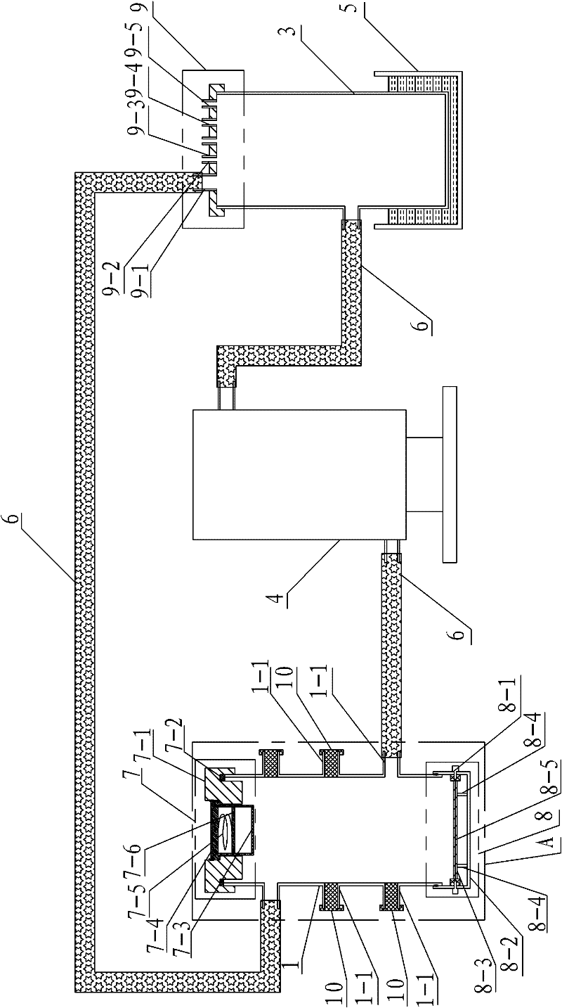
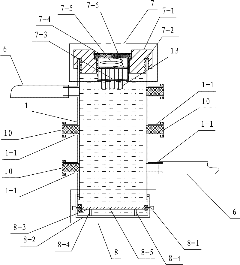
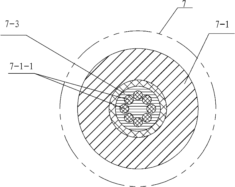
[0007] Specific implementation mode one: combine Figure 1-Figure 4 Describe this embodiment, the local electroplating device of tiny parts of this embodiment comprises plating tank tank body 1, adjustment tank tank body 3, plating solution circulating filter 4, water bath device 5 and three rubber hoses 6, and adjustment tank 3 is arranged on the water bath In the device 5, the plating tank body 1, the plating solution circulation filter 4 and the adjustment tank 3 are arranged in sequence from left to right, and the plating solution circulation filter 4 and the adjustment tank 3 are connected through a rubber hose 6, and the local electroplating of tiny parts The device also includes a plating tank cover 7, an anode bottom tank 8, an adjustment tank cover 9, a plurality of nozzle plugs 10 and a group of tiny parts 13, a plurality of nozzles 1-1 are set on the plating tank body 1, and the plating One nozzle 1-1 of the tank body 1 communicates with the plating solution circula...

specific Embodiment approach 2

[0013] Specific implementation mode two: combination figure 1 and figure 2 To describe this embodiment, a plurality of nozzles 1-1 of this embodiment are arranged symmetrically on the body 1 of the plating tank, and the plurality of nozzles 1-1 on the same side are arranged up and down. In this way, a plurality of nozzles 1-1 are arranged symmetrically on both ends of the side wall of the plating tank body 1, and two nozzles 1-1 can be selected to enter and exit the plating solution according to research needs, which is not only easy to operate, but also can be used as a spare. Other compositions and connections are the same as in the first embodiment.

specific Embodiment approach 3

[0014] Specific implementation mode three: combination figure 1 and figure 2 This embodiment is described, the anode bottom tank body 8-2 of this embodiment is screwed to the plating tank body 1 . In this way, the anode bottom tank body 8-2 is connected with the plating tank body 1 with threads, and the raw material tape is wound between the threads to prevent the leakage of the plating solution. At the same time, according to the different electroplating systems, anodes with different anode materials can also be made. The bottom tank body 8-2 can be replaced at any time as required. Other compositions and connections are the same as those in Embodiment 1 or Embodiment 2.

[0015] Specific implementation mode four: combination figure 1 and Figure 5 To illustrate this embodiment, the adjustment tank cover 9 of this embodiment is provided with an adjustment tank plating solution circulation port 9-1, an electrode insertion port 9-2, a temperature sensor insertion port 9-3,...


PUM


Abstract

The invention discloses a local electroplating device for micro parts, relates to an electroplating device and aims to solve the problem that the conventional plating tank does not have a suitable space for containing the micro parts which need electroplating locally and is not provided with an interface connected with plating solution circulation equipment so as not to realize the local electroplating of the micro parts in the plating solution circulation state. A plurality of orifices are formed on a plating tank body. A part slot is formed in a sealed cover and is provided with a pluralityof arrays of part placement ports. A group of micro parts are inserted into the part placement ports. The sealed cover is covered on the plating tank body. A cathode conductive cover and a cathode conductive connection cover are arranged on the sealed cover. The cathode conductive connection cover is arranged in a cathode test piece placement cavity. The lower end of the plating tank body is arranged in an anode bottom groove body. An anode plate is positioned in the anode bottom groove body. An anode support frame is supported between the anode plate and the anode bottom groove body. A groove cover of a regulating groove is buckled on a regulating groove body. The local electroplating device is suitable for electroplating the micro parts.

Description

technical field [0001] The invention relates to an electroplating device, in particular to a partial electroplating device for tiny parts, and belongs to the technical field of metal surface treatment. Background technique [0002] With the development of precision machining technology, the size of the workpiece processed by electrodeposition technology is getting smaller and smaller, the shape is more and more complex, and more and more parts need partial electroplating. Moreover, with the development of rare and precious metal environmental protection electrodeposition technology and the use of new electrolytes such as ionic liquids, the plating solution needs to be circulated and filtered to maintain a stable working state. However, the existing plating tank has no suitable space to place tiny parts that need to be partially electroplated, and there is no interface for connecting the plating solution circulation equipment, so the partial electroplating of tiny parts under...

Claims


Application Information

Patent Timeline
Patent Type & Authority Patents(China)
IPC IPC(8): C25D17/02C25D21/18C25D5/02
Inventor 张锦秋马今朝安茂忠王晓伟陈桂林
Owner HARBIN INST OF TECH
Why Eureka
Try Eureka