
Quick plaster ionic perforating machine perforating head driver

A driver and punching machine technology, applied in metal processing, etc., can solve the problems of low production efficiency and poor synchronization of drilling, and achieve the effects of high production efficiency, improved production efficiency and strong reliability

Inactive Publication Date: 2011-04-27
SHENYANG NORMAL UNIV
View PDF5 Cites 0 Cited by
  • Summary
  • Abstract
  • Description
  • Claims
  • Application Information

AI Technical Summary

Problems solved by technology

[0003] In order to solve the technical problems of low production efficiency and poor synchronization of punching existing in the drive power supply of the punching head of the existing ion plaster punching machine, the present invention provides a fast punching head of the plaster ion punching machine with high production efficiency and good synchronization driver

Method used

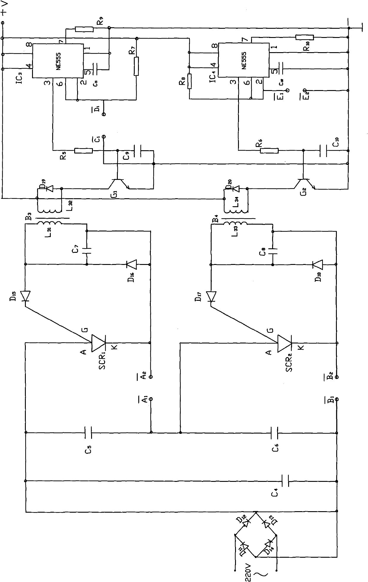

Image

  • Quick plaster ionic perforating machine perforating head driver
  • Quick plaster ionic perforating machine perforating head driver
  • Quick plaster ionic perforating machine perforating head driver

Examples


Embodiment

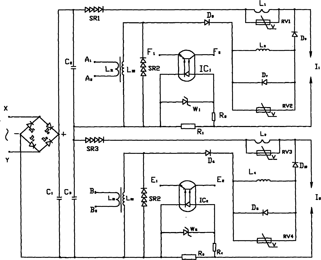
[0016] combine figure 2 , Figure 5 , further explain the main circuit of the driver:

[0017] The main part of the driver is connected to 220V-110V at both ends of X and Y, adjustable 50H Z comminicate. via diode D 1 -D 4 The composed rectified full bridge is transformed into pulsating DC, which is output from the "+" and "-" ends of the bridge. Through capacitance C 1 Filter to obtain a smooth DC voltage. by capacitance C 2 , high pressure stacking SR 1 , Transformer H 1 , high voltage silicon stack SR 2 , Diode D 5 ,D 7 ,D 9 , inductance L 1 , L 2 , varistor RV 1 , RV 2 , forming the driving electrode pair I 1 (spark plug) drive circuit.

[0018] by capacitance C 3 , high voltage silicon stack SR 3 , SR 4 , Transformer H 2 , Diode D 6 ,D 8 ,D 10 , and inductance L 3 , L 4 , varistor RV 3 , RV 4 , constituting the driving electrode pair I 2 (Spark plug) drive circuit. Drive electrode pair I 1 and drive electrode pair I 2 The circuit structur...


PUM


Abstract

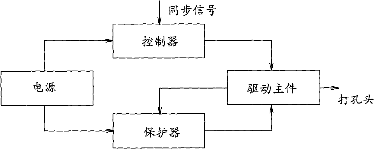
The invention discloses a quick plaster ionic perforating machine perforating head driver, which is designed to solve the technical problems of low production efficiency and low perforating synchronism of the conventional ionic plaster perforating machine perforating head driving power source. The driver consists of four parts, namely a power source, a controller, a protector and a driver master part, wherein the power source provides electronic circuit DC for the controller and the protector, provides 220V utility power through the controller and provides 220-110V adjustable 50Hz AC for the driver master part through the protector; a diver master part is designed into two completely symmetric structures of a drive electrode pair I1 and a drive electrode pair I2 through capacitors C1, C2 and C3, receives a perforating control signal from the controller and ensures that two circuit spark plugs I1 and I2 alternately provides ignition high voltage and instant heavy current after the high voltage according to the perforating instruction signal of the controller; and plasters between the spark plugs are broken through to form small arcs through the high voltage, and the small arcs causes strong arcs to realize perforation. Compared with the prior art, the driver has the advantages of high arc generating frequency and production efficiency, good synchronism, simple structure and high reliability.

Description

Technical field: [0001] The invention relates to a driver, in particular to a driver for a punching head of a rapid plaster ion punching machine. It is the core component of the non-mechanical punching equipment specially configured for the plaster production line of the pharmaceutical factory. Background technique: [0002] At present, the driving power of the punching head of the ion plaster punching machine in the prior art has the disadvantages of low production efficiency and poor synchronization of punching. Invention content: [0003] In order to solve the technical problems of low production efficiency and poor synchronization of punching existing in the drive power supply of the punching head of the existing ion plaster punching machine, the present invention provides a fast punching head of the plaster ion punching machine with high production efficiency and good synchronization driver. It consists of four parts: power supply, controller, protector and drive ma...

Claims


Application Information

Patent Timeline
Patent Type & Authority Applications(China)
IPC IPC(8): B26F1/28B26D5/08
Inventor 高田山
Owner SHENYANG NORMAL UNIV
Learn More