
Electromagnetic heating superconducting heating system

A technology of heating system and electromagnetic heating device, applied in electric heating system, heating system, heating method, etc., can solve the problems of low heating efficiency of heating system, affecting product service life, and high cost of heating system, and achieves good heating effect and high energy efficiency. The effect of improved thermal efficiency and low manufacturing cost

Inactive Publication Date: 2011-04-20
李东升 +2
View PDF3 Cites 3 Cited by
  • Summary
  • Abstract
  • Description
  • Claims
  • Application Information

AI Technical Summary

Problems solved by technology

[0003] 1: Liquid heating: This type of heating method needs to pressurize the liquid in the pipeline, so that the heated liquid can circulate in the pipeline and bring the heat everywhere; however, due to the high pressure in the pipeline, the liquid Leakage is easy to occur; at the same time, because the liquid flows in the pipeline for a long time, it is easy to scale or oxidize and rust on the pipeline wall, which not only affects the heating efficiency, but also affects the service life of the product;
[0004] Two: Cable heating: laying cables in the floor or concrete for heating, due to the high resistance and high loss of the cables, the heating efficiency of the entire heating system is low;
[0005] Three: Electric heating film heating: using electric heating film heating, the heating efficiency is higher, but it is necessary to lay electric heating film on the entire surface to be heated, which makes the entire heating system cost higher

Method used


Image

  • Electromagnetic heating superconducting heating system
  • Electromagnetic heating superconducting heating system
  • Electromagnetic heating superconducting heating system

Examples


Embodiment Construction

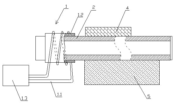
[0039] see figure 1 , an electromagnetic heating superconducting heating system related to the present invention, said system includes an electromagnetic heating device 1, a superconducting conduit heat transfer device 2, a temperature detection controller 3 and a floor 4,

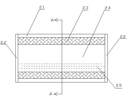
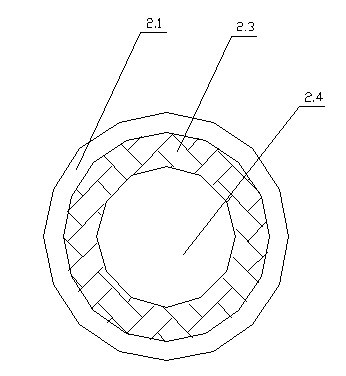
[0040] The superconductor heat transfer device 2 includes a superconductor 2.1, the two ends of the superconductor 2.1 are provided with plug caps 2.2, the superconductor 2.1 is laid under the floor 4, the superconductor 2.1 and the plugs at both ends The sealing cap 2.2 forms a closed cavity 2.4, and the inner wall of the superconductor 2.1 is adhered with a liquid-absorbing core 2.3, and the liquid-absorbing core 2.3 is a capillary structure, and the liquid-absorbing core 2.3 is made of wire mesh, porous ceramics, Sintered metal, metal fiber or cloth is formed as a lining close to the inner wall of the superconductor 2.1, and the cavity 2.4 is filled with superconducting liquid 2.5;

[0041] The electro...


PUM


Abstract

The invention relates to an electromagnetic heating superconducting heating system. The electromagnetic heating superconducting heating system comprises an electromagnetic heating device (1), a superconducting tube heat transfer device (2) and a floor (4), wherein the superconducting tube heat transfer device (2) comprises a superconducting tube (2.1); the superconducting tube (2.1) and plug sealing caps (2.2) at the two ends of the superconducting tube (2.1) form a sealed cavity (2.4); a fluid suction tube core (2.3) is adhered to the inner wall of the superconducting tube (2.1); superconducting fluid (2.5) is injected into the cavity (2.4); the electromagnetic heating device (1) comprises an electromagnetic heating line (1.1), a heat preservation layer (1.2) and an electromagnetic heating controller (1.3); the heat preservation layer (1.2) covers an outer tube wall at any end of the superconducting tube (2.1); the electromagnetic heating line (1.1) is wound on the heat preservation layer (1.2); and the two ends of the electromagnetic heating line (1.1) are connected with the electromagnetic heating controller (1.3). The electromagnetic heating superconducting heating system has the advantages of long service life, high heating efficiency and low cost.

Description

technical field [0001] The invention relates to an electromagnetic heating superconducting heating system. Background technique [0002] At present, conventional floor heating generally adopts the following methods: [0003] 1: Liquid heating: This type of heating method needs to pressurize the liquid in the pipeline, so that the heated liquid can circulate in the pipeline and bring the heat everywhere; however, due to the high pressure in the pipeline, the liquid Leakage is easy to occur; at the same time, because the liquid flows in the pipeline for a long time, it is easy to scale or oxidize and rust on the pipeline wall, which not only affects the heating efficiency, but also affects the service life of the product; [0004] Two: Cable heating: laying cables in the floor or concrete for heating, due to the high resistance and high loss of the cables, the heating efficiency of the entire heating system is low; [0005] Three: Electric heating film heating: using electr...

Claims


Application Information

Patent Timeline
Patent Type & Authority Applications(China)
IPC IPC(8): F24D13/04F24D19/00F24D19/10
Inventor 李东升包添成王小惠
Owner 李东升
Learn More