Vehicle headlamp system

A technology for headlights and vehicles, applied in the field of headlights, can solve problems such as recovery delay

Active Publication Date: 2013-04-03
KOITO MFG CO LTD
View PDF1 Cites 0 Cited by
  • Summary
  • Abstract
  • Description
  • Claims
  • Application Information

AI Technical Summary

Problems solved by technology

Therefore, before the initial setting of these vehicle height reference values ​​and reference steering angles is completed, the normal control of the leveling device and the rotation device is stopped, and the operation of the entire system is stopped during this period, and the return to the normal operation of the system is delayed.

Method used


Image

  • Vehicle headlamp system
  • Vehicle headlamp system
  • Vehicle headlamp system

Examples


Embodiment Construction

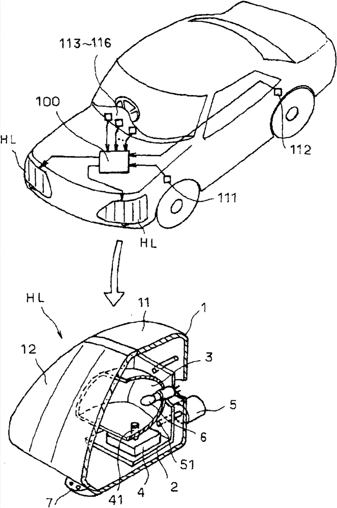
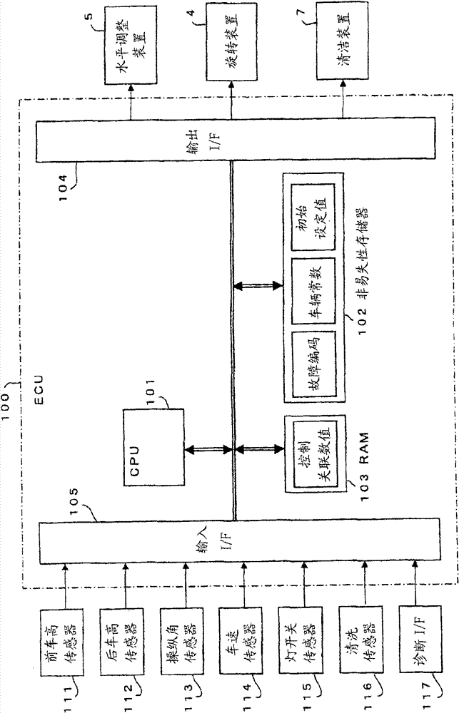
[0043] Hereinafter, embodiments of the present invention will be described with reference to the drawings. figure 1 It is a structural schematic diagram of an important part of a motor vehicle to which the system of the present invention is applied. Headlamps HL are respectively arranged on the left and right in the front part of the vehicle, and a plurality of control mechanisms for changing and controlling the light irradiation form such as the light irradiation direction are incorporated in each of these headlights HL. In this embodiment, as the control mechanism, a horizontal adjustment device for controlling the deflection of the light axis of the headlight HL in the vertical direction, a rotating device for controlling the deflection of the light axis of the headlight HL in the horizontal direction, It is a cleaning device for removing the sludge and dust adhering to the front lens of the headlamp. which is, figure 1 The schematic cross-sectional structure of the left ...


PUM


Abstract

A vehicle headlamp system includes a headlamp (HL) having multiple control devices (4, 5, 7) and an ECU (100). Each of the control devices (4, 5, 7) controls a light irradiation condition of the headlamp (HL). The ECU (100) stores vehicle constants, error code information and initialization information corresponding to different types of vehicle, and controls the control devices (4, 5, 7). When a vehicle type is changed, the ECU (100) selects at least one of the vehicle constants corresponding to the changed vehicle type, clears the stored error code information and the initialization information after selecting the at least one of the vehicle constants, stores initialization information corresponding to the changed vehicle type, and initializes the control devices (4, 5, 7). The ECU (100) recognizes dependencies between the control devices (4, 5, 7) and, if the control devices (4, 5, 7) include a first control device that is independent, executes normal control by the first control device directly after initializing the first control device.

Description

technical field [0001] The present invention relates to vehicle headlamps such as automobiles, and more particularly to a vehicle headlamp system having a function of automatically changing and controlling the light irradiation form such as the light irradiation direction of the headlamp. Background technique [0002] In recent years, as one of the purposes of improving driving safety of motor vehicles, headlight systems capable of appropriately and automatically controlling the light irradiation direction of headlights have been proposed. For example, there is a system comprising: a leveling device having a function of controlling the headlights according to changes in the inclination angle of the vehicle (the inclination angle along the front and rear direction of the vehicle) that accompany changes in the occupants of the vehicle and the loads. The function of controlling the change of light irradiation direction in the vertical direction; the rotating device has the func...

Claims


Application Information

Patent Timeline
Patent Type & Authority Patents(China)
IPC IPC(8): B60Q1/115
CPCB60Q1/12B60Q2200/38B60Q1/076B60Q1/10
Inventor 山崎敦之小西明
Owner KOITO MFG CO LTD
Why Eureka
Try Eureka