
Improvement in elevated track for a vehicle with a pneumatic propulsion system

A pneumatic propulsion and vehicle technology, which is applied in the direction of propulsion equipment railway systems, tracks, motor vehicles, etc., can solve the problem of no side protection structure, etc., and achieve the effect of light weight and reduced weight

Active Publication Date: 2011-04-13
奥斯卡·汉斯·沃尔夫冈·克斯特尔
View PDF5 Cites 4 Cited by
  • Summary
  • Abstract
  • Description
  • Claims
  • Application Information

AI Technical Summary

Problems solved by technology

[0009] - Requires side protection structures, which were not available in previous tracks;

Method used


Image

  • Improvement in elevated track for a vehicle with a pneumatic propulsion system
  • Improvement in elevated track for a vehicle with a pneumatic propulsion system
  • Improvement in elevated track for a vehicle with a pneumatic propulsion system

Examples


Embodiment Construction

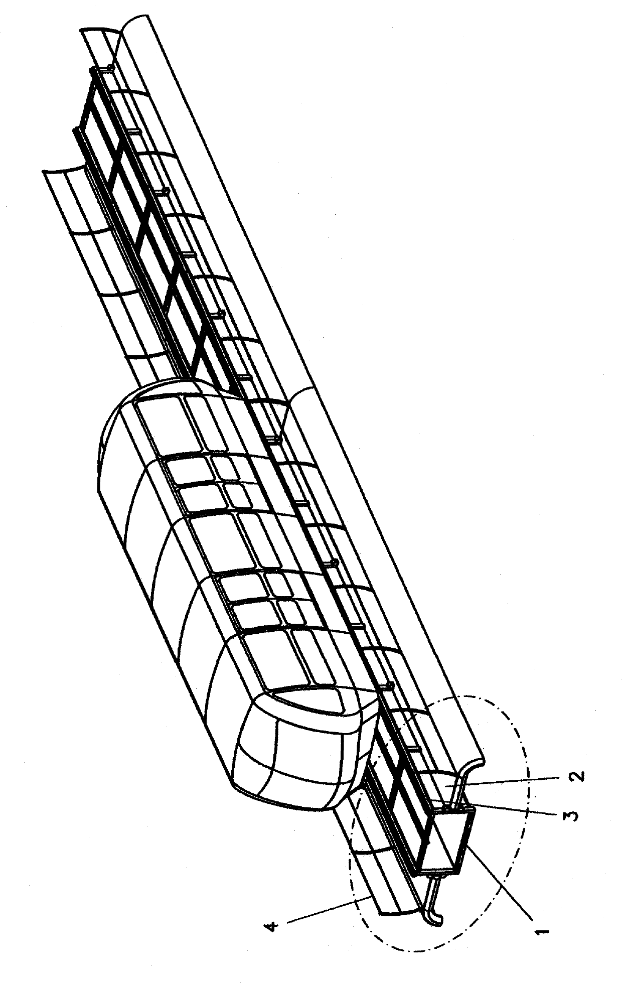
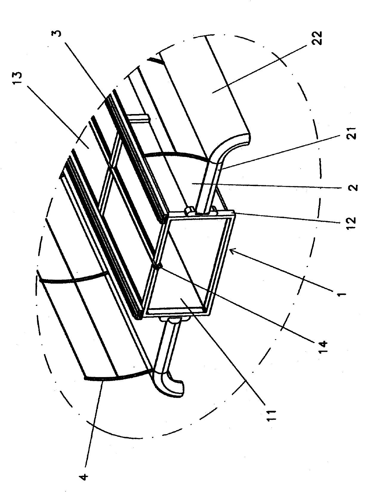
[0031] figure 1 and 2 Shows the general form of a modified elevated track, which is molded and self-supporting, and comprises a pneumatically propelled central duct (1) with side walkways fixed to the vertical walls (11) of the central duct (1) (2). The push catheter (1) has a reinforcement structure (12) in the form of a frame transverse to the catheter axis. The side walkways (2) have transverse reinforcements (21) engaged with the duct reinforcement frame (12). On the edge of the propulsion duct top (13), the rails are secured with "I" beams (3) commonly used in railways.

[0032] The propulsion duct transverse section (1) is preferably rectangular, with a central groove (14) on the upper surface (13) for the passage of the vehicle propulsion system.

[0033] Preferably, the side walkways (2) are provided with protective handrails (4) and downwardly curved edges (22) which, together with the central duct, define a covered area shielding pedestrians.

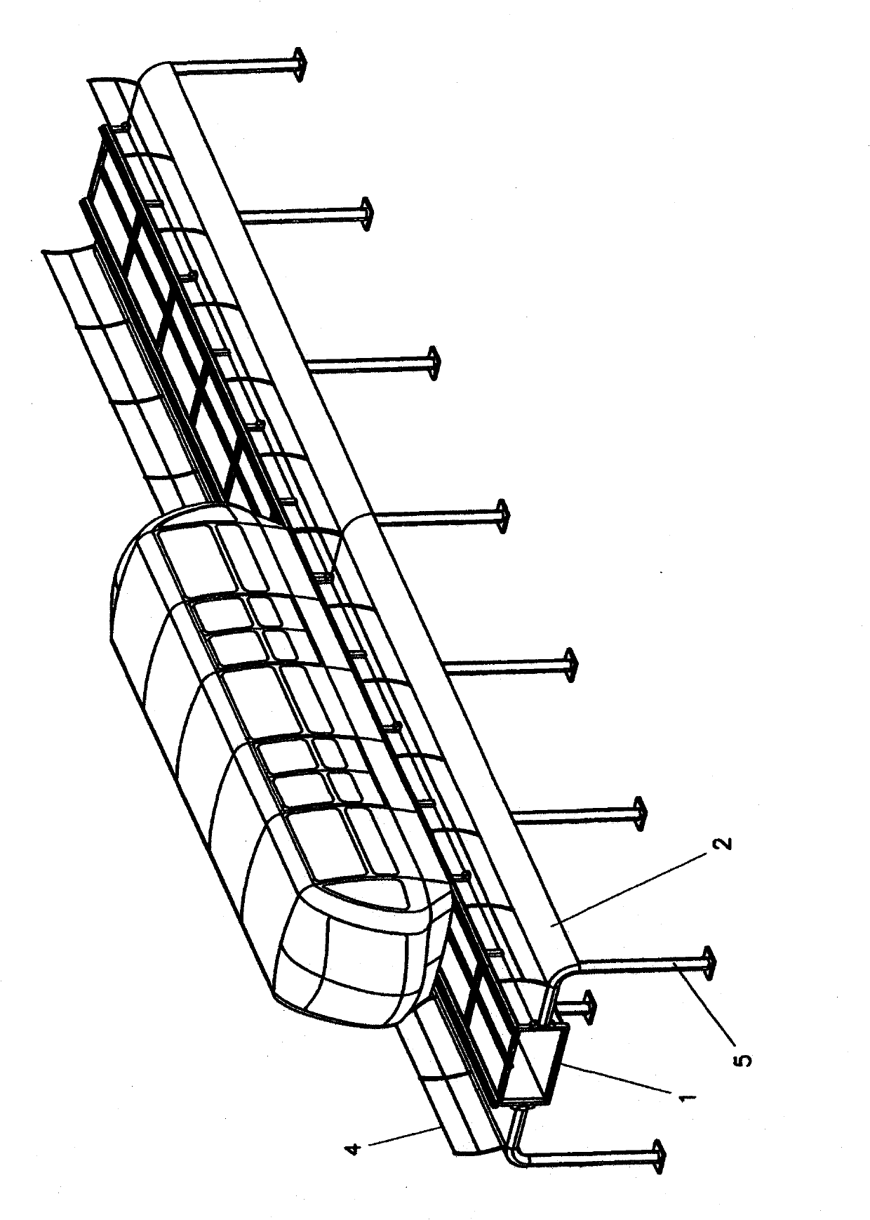
[0034] image 3 ...


PUM


Abstract

The invention refers to an elevated track to support and serve the pneumatic propulsion duct for transportation vehicles, for cargo or passengers. The improved elevated track is modular and self supporting and consists of a pneumatic propulsion central duct (1) on whose vertical walls (11) are fastened side walkways (2). The propulsion duct (1) has structural reinforcing (12) in the form of transverse frames on the duct axis. The side walkways (2) have transverse reinforcement (21) which unify with the duct reinforcing frames (12). On the propulsion duct (1) top edges (13) are fastened rails (3) in a 'I' beam format, traditionally used on railroads. A preferred transverse section of the propulsion duct (1) is rectangular, this having a central slot (14) on the top surface (13) for the passage of the vehicle propulsion system. Preferably, the side walkways (2) have protective handrails (4) and edges curved downwards (22) which with the central duct (1) define a covered area to shelter the pedestrians. One constructive option for the elevated track, formed with the propulsion duct (1) and the side walkways (2), which can be supported on pillars (5) positioned under the side walkways (2). In another constructive option, the elevated track can be suspended by vertical tie rods (6) fastened on the side walkways (2).

Description

technical field [0001] The present invention relates to an improvement in an elevated track for supporting and serving as a conduit for a pneumatic propulsion system of a transport vehicle for goods or personnel. Background technique [0002] Patent BR PI 7703372-8, filed by the same inventor on May 25, 1977, describes an elevated track for supporting and pneumatically propelling transport vehicles, the ends of which are supported by beams. The track is made of reinforced concrete and has a hollow transverse section with an upper groove for the passage of the vertical poles of the transport vehicles. [0003] Patents BR PI 8301706-2, BR PI 8503504-1 and BR PI 9502056-0, filed by the same applicant on April 4, 1983, July 19, 1985 and May 11, 1995 respectively, describe a An elevated track made of reinforced concrete has the same general idea as the aforementioned document. [0004] The track is expensive to construct from reinforced concrete, not least because of the deep f...

Claims


Application Information

Patent Timeline
Patent Type & Authority Applications(China)
IPC IPC(8): B61B13/12
CPCB61B13/122E01B25/10
Inventor 奥斯卡·汉斯·沃尔夫冈·克斯特尔
Owner 奥斯卡·汉斯·沃尔夫冈·克斯特尔
Learn More