
Electric lock with infrared status indication for preventing misoperation

A status indication and anti-misoperation technology, applied in the field of electrical locks, can solve the problems of electrode exposure, current disappearance, easy to cause misjudgment, etc., to avoid heat generation, detect circuit energy saving, and prevent electrical misoperation.

Inactive Publication Date: 2012-10-10
NR ELECTRIC CO LTD +1
View PDF1 Cites 0 Cited by
  • Summary
  • Abstract
  • Description
  • Claims
  • Application Information

AI Technical Summary

Problems solved by technology

[0005] 1. The electrodes of the lock are exposed and can be simply short-circuited with wires, which has the defect of artificial random operation
[0006] 2. It needs to be judged by whether there is current flowing through the operation circuit during the operation of the equipment. This judgment will be based on the short operation time, the self-holding of the operation relay after the button or switch is returned, and the current of the operation circuit will disappear. This It takes a short time to correctly judge whether the operation is successful and whether the equipment status is in place, which is easy to cause misjudgment

Method used


Image

  • Electric lock with infrared status indication for preventing misoperation
  • Electric lock with infrared status indication for preventing misoperation

Examples


Embodiment Construction

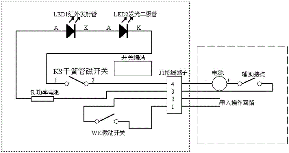
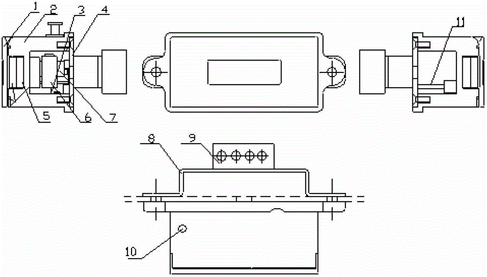
[0015] The present invention will be described in further detail below in conjunction with the accompanying drawings and specific embodiments.

[0016] The technical key points of the present invention are: 1. Transmitting equipment status information through infrared photoelectric signals; one of the characteristics of the electric lock is: the opening and closing node is a knife-shaped micro switch in the lock, and the rotation of the lock cylinder drives the pressing plate to connect Through the switch contact, the barrel-shaped lock cylinder is shown in the figure. It has a semicircular positioning concave hole, and a switch pressure piece. The metal shrapnel with a semicircular boss is fixed on the shell. When the lock cylinder shaft sees figure 2 7. When the switch is turned on by rotating it to a predetermined angle, the shrapnel happens to be (see figure 2 The boss in 3) is pressed into the spherical pit to play a positioning role. The electric lock also has a red L...


PUM


Abstract

The invention relates to an electric lock with an infrared status indication for preventing misoperation. The front side of the electric lock is provided with two holes, wherein a left hole is used for performing auxiliary positioning, and a right hole is a computer key hole; a magnetic switch and a power supply source and a light-emitting diode (LED) which are connected in series with the magnetic switch are arranged in the left hole; a lock core in the computer key hole is provided with a rotatable pressing block and a micro switch for connection; when the lock is unlocked, the pressing block is pressed towards the micro switch to ensure that a circuit is switched on; a positioning hole is formed on the lock core; a flexible sheet with hemispherical salient points is arranged on a lock shell outside the lock core; and when a key is used to unlock and rotates in place, the salient points are immersed into the positioning hole of the lock core for positioning. When the lock core rotates, the spring sheet is driven to close the micro switch, and when the lock core returns to the normal position, the micro switch is opened, so that an operation loop is switched on and switched off; and when the electric lock does not need operating, energy is not consumed inside the electric lock, so that a voltage reduction circuit does not generate heat, and the electric lock can be used safely for a long time.

Description

technical field [0001] The invention relates to a safety operation device, in particular to an electric lock suitable for a knife switch and a switch in a power system. Background technique [0002] For the safe operation of the equipment, the power system needs to control the electrical operation circuit. The electric lock is a control device that is connected in series in the operation circuit to prevent misoperation of the equipment. The electric lock is equipped with coded information, and is equipped with a lock switch and a state detection device. In actual operation, the special unlocking device can only connect the switch node of the electric lock when it reads out the coded information of the device and verifies whether it is correct. Open / close operation of electrical switching devices. [0003] Other existing electric locks basically have two electrodes in the two holes on the front of the lock body. When operating the device, use the two metal rods of the comput...

Claims


Application Information

Patent Timeline
Patent Type & Authority Patents(China)
IPC IPC(8): H01H9/20H01H9/16E05B47/00E05B49/00E05B65/00E05B17/22
Inventor 任金华陈勇
Owner NR ELECTRIC CO LTD
Learn More