Installation arrangement of satellite-borne magnetometer

A magnetometer, on-board technology, applied in the direction of the size/direction of the magnetic field, can solve the problems of increased risk of satellite in-orbit deployment, bulky, increased weight, etc., to optimize the layout design of the entire satellite, and to achieve strong engineering feasibility. , to avoid the effect of the design

Active Publication Date: 2011-04-13
八院云箭(北京)航天技术研究院有限公司
View PDF8 Cites 2 Cited by
  • Summary
  • Abstract
  • Description
  • Claims
  • Application Information

AI Technical Summary

Problems solved by technology

The stretching mechanism itself is bulky and complex in structure. Not only must a complete set of special magnetometer stretching mechanism be designed for each satellite, but also adds a certain weight to the design of the satellite platform, and consumes a lot of research and development funds. Disadvantages such as reduced satellite reliability and increased risk of satellite deployment in orbit

Method used


Image

  • Installation arrangement of satellite-borne magnetometer
  • Installation arrangement of satellite-borne magnetometer
  • Installation arrangement of satellite-borne magnetometer

Examples


Embodiment Construction

[0008] Below in conjunction with accompanying drawing and embodiment the present invention will be described in further detail

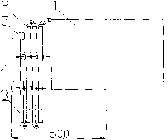
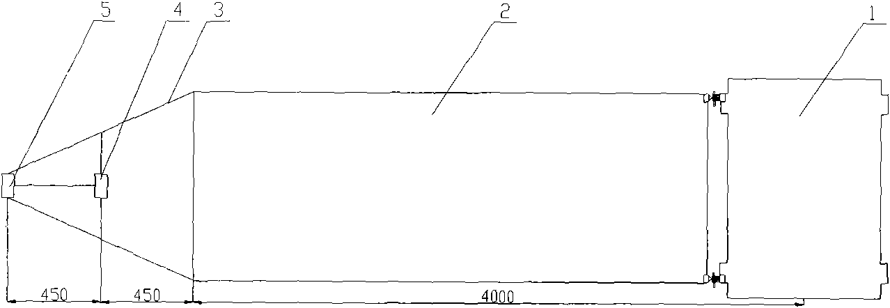
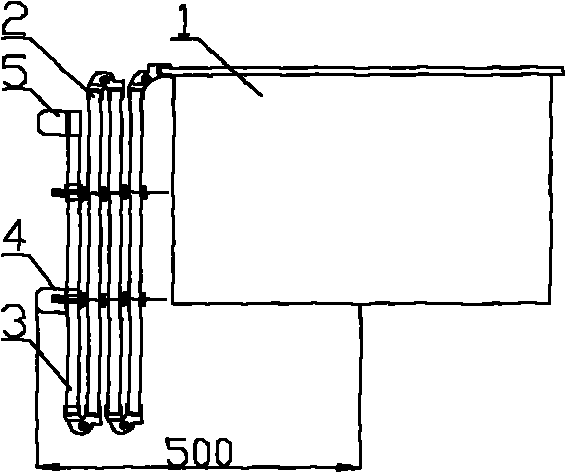
[0009] Such as figure 1 Shown is a schematic diagram of the outer side of the solar wing, which consists of a solar wing connected to a star and a solar wing sail. A bracket for installing a magnetometer is provided on the outer side of the solar wing. The bracket includes a magnetometer bracket 3, a magnetometer probe 4, The magnetometer probe consists of 5 components. The above-mentioned star body 1 is connected to the solar sail 2 through a hinge, and the solar wing sail 2 is connected to the magnetometer bracket 3 through a hinge; the above-mentioned magnetometer probe 4 and magnetometer probe 5 are respectively fixed on the magnetometer bracket by screws. 3 on. Such as figure 2 Shown is a schematic diagram of the installation position of the magnetometer probe. The magnetometer probe 5 is located at the end of the solar wing sail of the sate...


PUM


Abstract

The invention discloses installation arrangement of a satellite-borne magnetometer, comprising solar wings connected with a satellite body and a solar wing sailboard, wherein a bracket for installing the magnetometer is arranged at the outer side of the solar wing. The satellite body is connected with the solar wing sailboard through a hinge; the solar wing sailboard is connected with the bracketof the magnetometer through a hinge; and probes of the magnetometer are respectively fixed on the bracket of the magnetometer through bolts. The invention has simple theory and engineering feasibility, meets the technical requirements of specially using an extension mechanism to ensure that a residual magnetic index at installation position of the two probes of the magnetometer is less than 0.5 nT, optimizes the whole satellite arrangement design, saves weight for the whole satellite design, and avoids the design of complex extension mechanism. The invention has the advantages of shortening development cycle, saving development cost and the like.

Description

technical field [0001] The present invention relates to the overall technical field of satellite magnetometers, in particular to a method for arranging the positions of magnetometers for Mars satellites. Background technique [0002] Magnetometer loads are widely used in satellites and are a relatively wide range of magnetic field detection instruments. The use of this type of load has certain special requirements, and it needs to avoid the influence of the satellite’s own magnetic field on it. Therefore, in the overall structure of the satellite When arranging, a special device / mechanism is generally required to install the position of the magnetometer to meet the requirement of the working distance of the magnetometer. [0003] At present, most of the magnetometers used on satellites adopt a 2-fold or 3-fold stretching mechanism in the overall structure of the satellite. The magnetometer is installed at the end of the stretching mechanism, and the satellite is unfolded aft...

Claims


Application Information

Patent Timeline
Patent Type & Authority Applications(China)
IPC IPC(8): G01R33/02
Inventor 方宝东
Owner 八院云箭(北京)航天技术研究院有限公司
Why Eureka
Try Eureka