Handover processing method in case of failed Ethernet automatic protection switching (EAPS) looped network link and switching equipment
A technology for link failure and switching equipment
- Summary
- Abstract
- Description
- Claims
- Application Information
AI Technical Summary
Problems solved by technology
Method used
Image
Examples
Embodiment 1
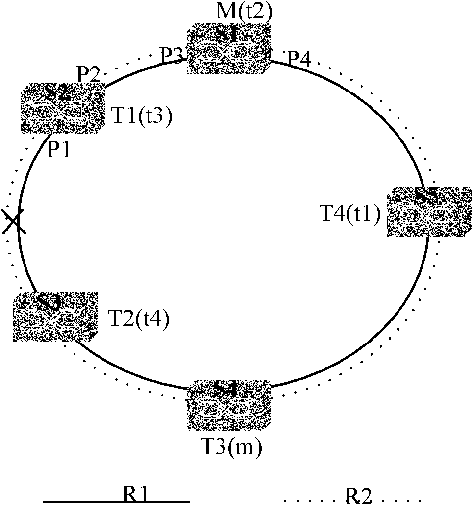
[0038] Such as figure 2 As shown in FIG. 2 , it is a schematic diagram of a link failure between transit nodes when the master nodes are located in different switches when there are two EAPS rings on one physical Ethernet ring. Five switches S1, S2, S3, S4, and S5 are connected to form a physical Ethernet ring, and there are two EAPS rings R1 and R2 on the physical Ethernet ring. The master node M of the EAPS ring R1 is on the switch S1, and its transit nodes are denoted by T, that is, T1, T2, T3 and T4 are on the switches S2, S3, S4 and S5 respectively. The master node of EAPS ring R2 is on S4, and its transit node is represented by t, that is, t1, t2, t3 and t4 are on switches S5, S1, S2 and S3 respectively.
[0039] If the link between S2 and S3 fails, both S2 and S3 will detect the failure of the port connected to the ring network. After the transmission nodes T1 and t3 represented by S2 detect that the link where port P1 is located is faulty, the operations performed b...
Embodiment 2
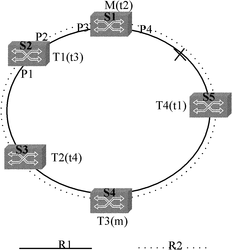
[0051] Such as image 3 , the link between S1 and S5 is faulty, and the EAPS nodes on both S1 and S5 will detect the link fault; after S1 detects that port P4 is faulty, the processing flow of switch S1 is as follows:
[0052] (1) as the master node M of the ring R1, send a ring failure refresh message to the ring through the port P3;
[0053] (2) as the transit node t2 of the ring R2, send a loop failure message and a loop failure refresh message to the ring through the port P3;
[0054] (3) Notify the forwarding table refreshing unit to refresh the forwarding table of the faulty port P4.
[0055] (4) notify the port forwarding mode processing unit to set port P4 about the data VLAN of R1 and R2 and the control VLAN as blocking mode;
[0056] After the switch S5 detects a port failure, the processing is the same as that of the port P1 failure detected by S2 in Embodiment 1.
[0057] The processing of S2 and S3 is the same as the processing of S5 in Embodiment 1.
[0058] ...
Embodiment 3
[0060] Such as Figure 4 , the master node M of ring R1 and the master node m of ring R2 are both located on switch S1. If the link between S1 and S5 fails, the processing flow of switch S1 is as follows:
[0061] (1) notify the port forwarding processing unit to set the data VLAN about the ring R1 and the ring R2 on the port P3 to be the forwarding mode;
[0062] (2) M and m send a loop failure refresh message to the ring respectively through port P3;
[0063] (3) M and m refresh the forwarding table of port P4.
[0064] (4) notify the port forwarding mode processing unit to set the data VLAN and the control VLAN about R1 and R2 on the port P4 as blocking mode;
[0065] The processing of S5 is the same as the processing of S2 in Embodiment 1.
[0066] The processing of S2, S3 and S4 is the same as that of S5 in Embodiment 1.
PUM
 Abstract
Description
Claims
Application Information
 - R&D
- Intellectual Property
- Life Sciences
- Materials
- Tech Scout
- Unparalleled Data Quality
- Higher Quality Content
- 60% Fewer Hallucinations
Browse by: Latest US Patents, China's latest patents, Technical Efficacy Thesaurus, Application Domain, Technology Topic, Popular Technical Reports.
© 2025 PatSnap. All rights reserved.Legal|Privacy policy|Modern Slavery Act Transparency Statement|Sitemap|About US| Contact US: help@patsnap.com


