On-line oil particle pollution degree detection sensor based on optical sensing
A detection sensor and optical sensing technology, which is applied in the field of sensors, can solve the problems of component on-line oil detection sensor measurement error, large impact on measurement results, unfavorable on-line detection, etc., to achieve accurate measurement, increase use convenience, Correct the effect of photoelectric conversion drift
- Summary
- Abstract
- Description
- Claims
- Application Information
AI Technical Summary
Problems solved by technology
Method used
Image
Examples
Embodiment 1
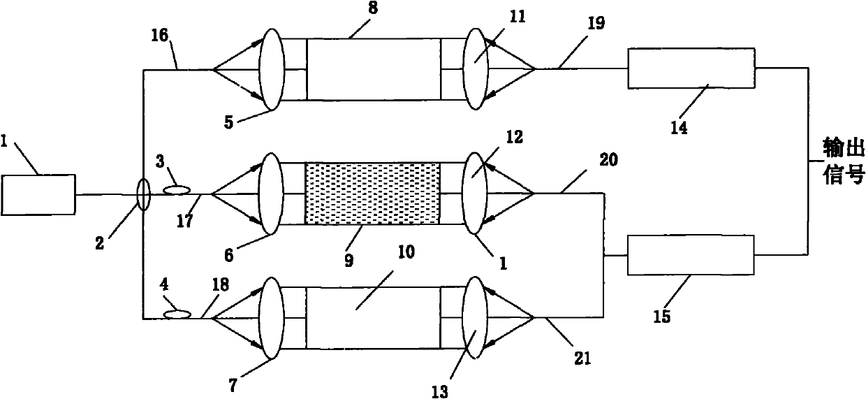
[0025] Such as figure 1 As shown, the online oil particle pollution degree detection sensor based on optical sensing is mainly composed of a light source 1, a 1×3 optical coupler 2, a first adjustable optical filter 3, a second adjustable optical filter 4, a first self- Focusing lens 5, second self-focusing lens 6, third self-focusing lens 7, first reference optical path oil pool 8, measurement oil pool 9, second reference optical path oil pool 10, fourth self-focusing lens 11, fifth self-focusing Lens 12, the sixth self-focusing lens 13, the first optical detector 14, the second optical detector 15, the first incident optical fiber 16, the second incident optical fiber 17, the third incident optical fiber 18, the first outgoing optical fiber 19, the second The outgoing optical fiber 20 and the third outgoing optical fiber 21 are formed; the input end of the 1×3 optical coupler 2 is connected with the light source 1 by the optical fiber, and the output end of the 1×3 optical c...
Embodiment 2
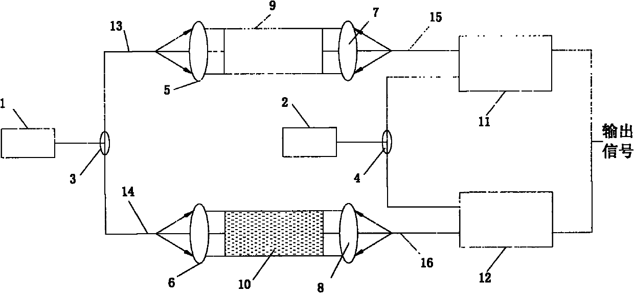
[0035] Such as figure 2 As shown, the online oil particle pollution degree detection sensor based on optical sensing is mainly composed of the first light source 1, the second light source 2, the first 1×2 optical coupler 3, the second 1×2 optical coupler 4, the first Self-focusing lens 5, second self-focusing lens 6, third self-focusing lens 7, fourth self-focusing lens 8, reference optical path air pool 9, measuring optical path oil pool 10, first photodetector 11, second photodetector 12. The first incident optical fiber 13, the second incident optical fiber 14, the first outgoing optical fiber 15, and the second outgoing optical fiber 16 are formed. The input end of the first 1×2 optical coupler 3 is connected to the first light source 1 by an optical fiber, and the first The output end of the 1×2 optical coupler 3 is divided into two paths, which are respectively connected to one end of the first incident optical fiber 13 and the second incident optical fiber 14, and the...
PUM
 Abstract
Description
Claims
Application Information
 - R&D
- Intellectual Property
- Life Sciences
- Materials
- Tech Scout
- Unparalleled Data Quality
- Higher Quality Content
- 60% Fewer Hallucinations
Browse by: Latest US Patents, China's latest patents, Technical Efficacy Thesaurus, Application Domain, Technology Topic, Popular Technical Reports.
© 2025 PatSnap. All rights reserved.Legal|Privacy policy|Modern Slavery Act Transparency Statement|Sitemap|About US| Contact US: help@patsnap.com


