
Steel plate winding device

A technology of steel coils and steel plates, applied to other manufacturing equipment/tools, manufacturing tools, etc., can solve the problem of low productivity

Inactive Publication Date: 2011-04-06
DONGMYUNG MACHINERY
View PDF6 Cites 0 Cited by
  • Summary
  • Abstract
  • Description
  • Claims
  • Application Information

AI Technical Summary

Problems solved by technology

[0006] Furthermore, according to the coiling device of the steel plate for welding wire of the prior art, since it is wound on a single bobbin, the productivity is very low.

Method used


Image

  • Steel plate winding device
  • Steel plate winding device
  • Steel plate winding device

Examples


Embodiment Construction

[0038] Hereinafter, preferred embodiments of the steel plate coiling device according to the present invention will be described in detail with reference to the drawings.

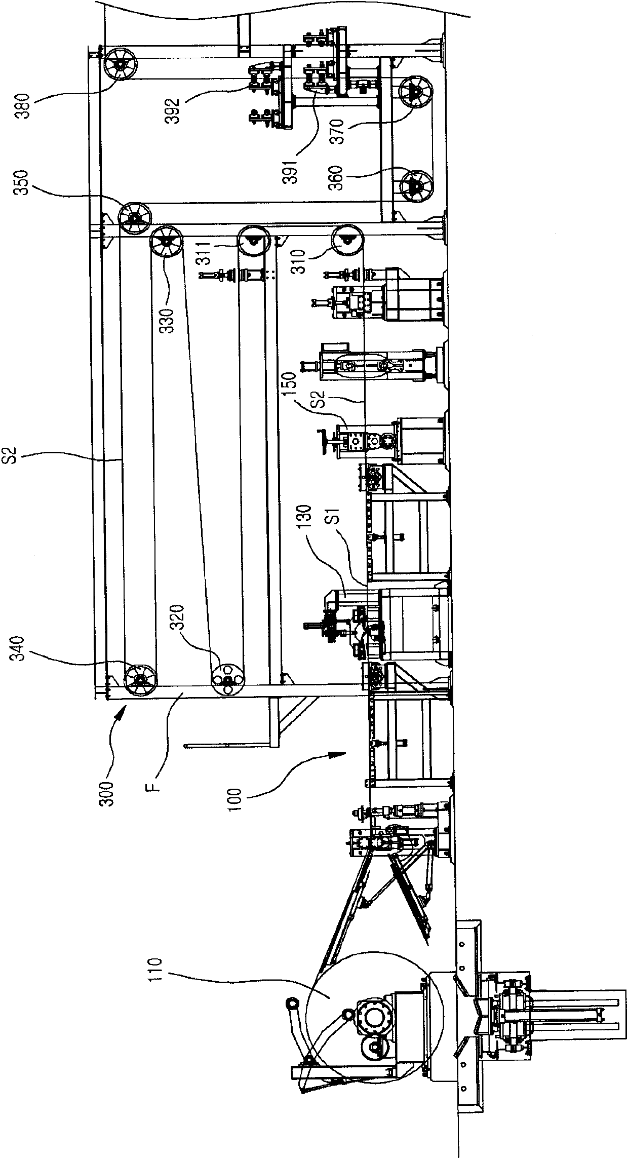
[0039] The steel plate coiling device according to the present invention includes a supply unit 100 , a first transfer unit 300 , a second transfer unit 500 and a rewind unit 700 .

[0040] Wherein, the supply unit 100 includes a drum 110 , a welding unit 130 and a slitting unit 150 .

[0041] A plurality of steel plates having a predetermined length and width, which are used as steel plates for welding wire, are wound around the drum 110 .

[0042] The welding unit 130 welds the plurality of steel plates guided from the drum in the longitudinal direction to form the first steel plate S1.

[0043] The slitting unit 150 uses the welding unit 130 to slitting (slitting) the plurality of narrow second steel plates S2 formed by extending the first steel plate S1 in the longitudinal direction.

[0044] In gener...


PUM


Abstract

The invention provides a steel plate winding device, comprising a round barrel wound with a plurality of steel plates of preset length and width; a welding unit for welding the steel plates from the round barrel according to the length direction to form a first steel plate; a supplying unit with a vertical cutting unit for vertically cutting the first steel plate into a plurality of second steel plates, wherein the second steel plate has the width narrower than that of the first steel plate; a first transfer unit for transferring the second steel plates and keeping a certain interval between the second steel plates; a second transfer unit for guiding the second steel plate transferred by the first transfer unit to make each second steel plate actually with same cross section length; and arewinding unit with a bobbin for uniformly winding each second steel plate.

Description

technical field [0001] The invention relates to a steel plate coiling device, in particular to a steel plate coiling device capable of continuously and effectively coiling longitudinally cut steel plates. Background technique [0002] There are many kinds of welding wires for general welding, especially the tubular welding wire (flux cored wire) is manufactured by making a steel plate into a hollow tubular shape, and then filling the inside with flux (flux). [0003] In this case, the steel plate for welding wire is produced by slitting a steel plate for welding wire having a predetermined width and length into a narrow steel plate, and then continuously welding a plurality of narrow steel plates thus formed in the longitudinal direction. [0004] As mentioned above, the steel plate for welding wire is produced according to the prior art, that is, when the narrow steel plate is produced, the steel plate for welding wire having a predetermined width and length is first slitti...

Claims


Application Information

Patent Timeline
Patent Type & Authority Applications(China)
IPC IPC(8): B23P23/04
Inventor 崔文锡金炯同
Owner DONGMYUNG MACHINERY
Learn More