
Box-type dust collecting device

A dust-collecting device and box-type technology, applied in the field of separation, can solve the problems of low efficiency and poor dust-collecting effect, and achieve the effects of convenient and simple operation, improved filtering effect, and improved dust-collecting efficiency.

Inactive Publication Date: 2011-04-06
CHONGQING POLYCOMP INT
View PDF4 Cites 3 Cited by
  • Summary
  • Abstract
  • Description
  • Claims
  • Application Information

AI Technical Summary

Problems solved by technology

[0004] In view of this, the embodiment of the present application provides a box-type dust collection device, which has a good dust collection effect on chopped wool yarn, and is convenient and efficient to clean, so as to solve the problems of poor dust collection effect and low efficiency of existing dust collectors

Method used


Image

  • Box-type dust collecting device
  • Box-type dust collecting device
  • Box-type dust collecting device

Examples


Embodiment 1

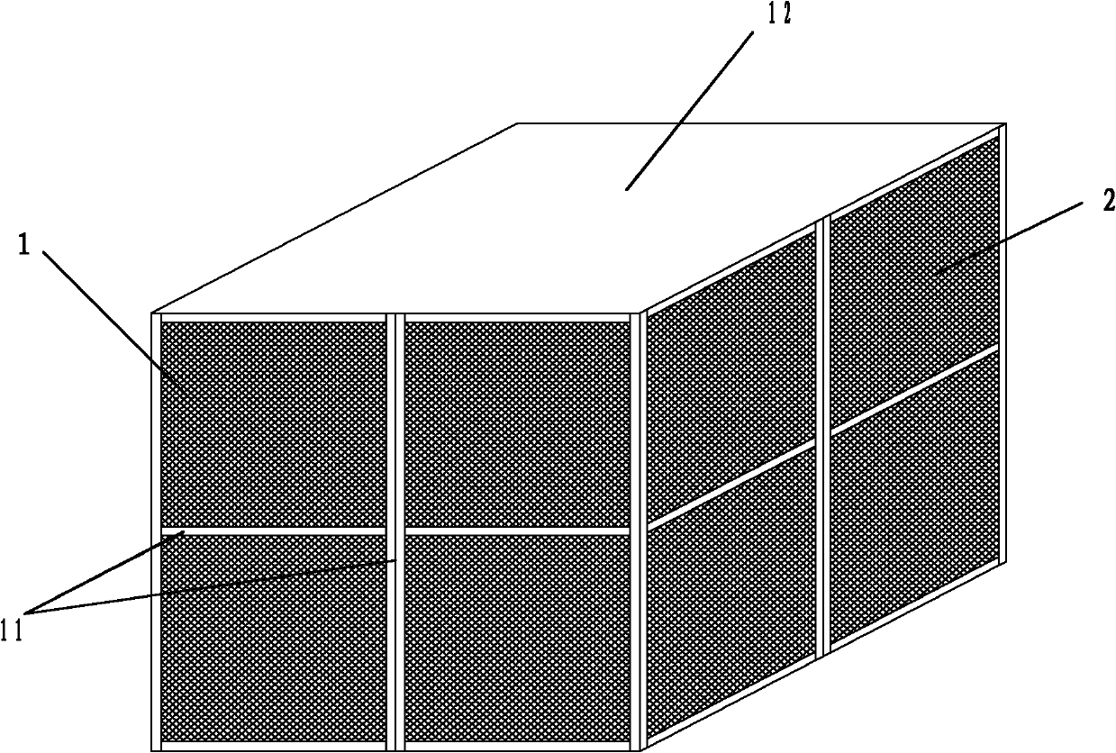
[0029] figure 1 It is a schematic structural diagram of a box-type dust collection device provided in the embodiment of the present application.

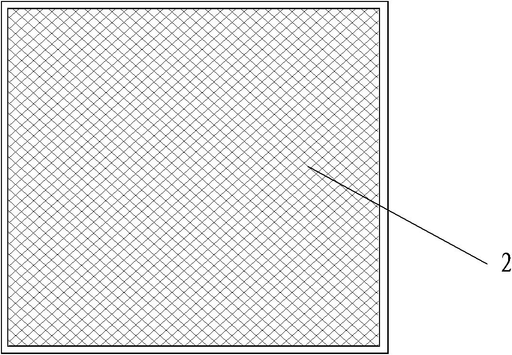
[0030] like figure 1 As shown, the box-type dust collection device includes: a support 1, a vertical plate 2 fixed on the side of the support 1 and a filter cotton (not shown in the figure) fixed on the vertical plate 2 .

[0031] like figure 1 As shown, the bracket 1 is a three-dimensional rectangle, and its top 11 is an integral plate, which seals the top. The bottom of the bracket 1 is not sealed and is left as an opening. The side of the support 1 is a plurality of support bars 12, and the four sides of the support 1 are divided into multiple pieces by the plurality of support bars 12. In the embodiment of the present application, the support bars 12 evenly divide each side of the support 1 into four pieces. piece.

[0032] like figure 1 As shown, the vertical plate 2 is installed on the support rod 12 of the support 1, an...

Embodiment 2

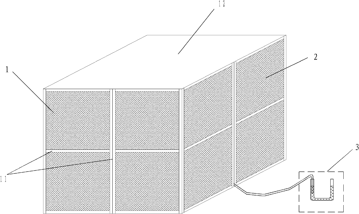
[0036] image 3 It is a schematic structural diagram of another box-type dust collection device provided in the embodiment of the present application.

[0037] like image 3 As shown, the box-type dust collection device also includes: a pressure measuring device (not shown in the figure) and a pressure indicating device 3, wherein:

[0038] The pressure measuring device is located inside the support 1 and is used to measure the gas pressure inside the support 1 . The pressure indicating device 3 is located outside the bracket 1 and is connected with the pressure measuring device to display the measurement results of the pressure measuring device.

[0039] When the box-type dust collection device is working, if it is blocked, its internal pressure will inevitably increase. It will be measured by the pressure measuring device and displayed on the pressure display device, so that the operator can know the box-type dust collector in time. Whether the dust device is blocked.

...


PUM


Abstract

The invention discloses a box-type dust collecting device, which comprises a bracket, vertical plates and filter wool, wherein the bracket has a three-dimensional structure, the top of the bracket is sealed, the bottom of the bracket is provided with an opening, and supporting rods are arranged on the lateral surfaces of the bracket; the vertical plates are detachably arranged on the supporting rods of the bracket, and the vertical plates are provided with grids for fully covering the four lateral surfaces of the bracket; and the filter wool is detachably fixed on the vertical plates on the inner lateral surfaces of the bracket, and the filter wool fully covers the grids on the vertical plates. Once the box-type dust collecting device is plugged during use, after an operator halts, the vertical plates are detached, then new filter wool is exchanged, the vertical plates are arranged on the bracket for startup production, and the exchanged filter wool can be separately cleaned and reclaimed with short cut wool yarns, so the operation is convenient and simple, and the dust collecting efficiency is improved.

Description

technical field [0001] This application relates to the field of separation, in particular to a box-type dust collecting device. Background technique [0002] Chopped glass fiber is one of the important reinforcement materials for resin matrix composites. In the existing chopped glass fiber production process, the chopped wool yarn in the chopped glass fiber is usually collected and recovered by a pulse bag filter. [0003] Through research on the prior art, the inventor found that: due to the large amount of chopped wool yarn, it is easier to adhere to the bag and block the dust collector, which will affect the dust collection effect. If the chopped wool yarn is mixed with chopped glass fiber It will also reduce the quality of chopped glass fiber products, and once the dust collector is blocked, it must be shut down for a long time for cleaning, and the dust collection efficiency is low. Contents of the invention [0004] In view of this, the embodiment of the present ap...

Claims


Application Information

Patent Timeline
IPC IPC(8): B01D46/30B01D46/42
Inventor 曾和平刘楷斌
Owner CHONGQING POLYCOMP INT
Learn More