
Grounding structure

A technology of grounding structure and contact piece, which is applied to the rack/frame structure, circuit layout on the support structure, cooling/ventilation/heating transformation, etc., which can solve the left and right deviation of the circuit board installation and the inability of the circuit board to be fully integrated Grounding and other issues, to achieve the effect of simple structure, stable grounding performance, and good heat dissipation

Inactive Publication Date: 2011-03-30
南京深科博业电气股份有限公司
View PDF5 Cites 2 Cited by
  • Summary
  • Abstract
  • Description
  • Claims
  • Application Information

AI Technical Summary

Problems solved by technology

[0005] The technical problem to be solved by the present invention is to avoid the left and right deviation of the general circuit board guide groove due to the deviation of the welding assembly process, and the general circuit board cannot be integrated with the equipment due to loose fixing nuts and fully grounded

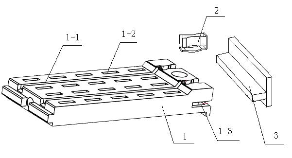
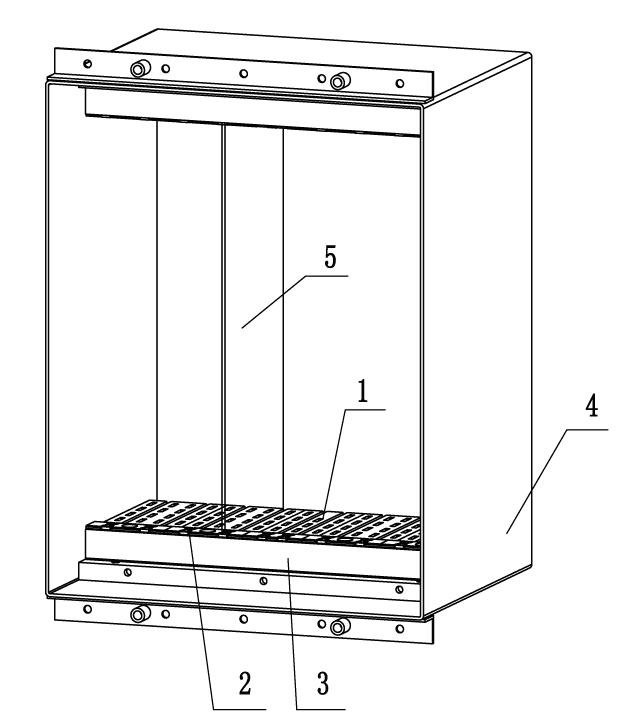
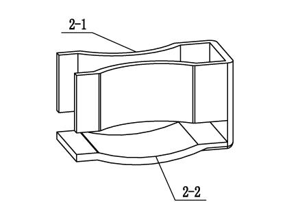
Method used


Image

  • Grounding structure
  • Grounding structure
  • Grounding structure

Examples


Embodiment Construction

[0013] The present invention will be further described below in conjunction with the accompanying drawings.

[0014] Such as Figure 1-3 As shown, a grounding structure includes a casing 4, a T-shaped metal bracket 3 located in the casing 4, and a guide block 1; 1-1, and the slot 1-3 matching the T-shaped tail of the metal bracket 3, the guide groove 1-1 runs through the upper surface of the guide groove block 1 along the axial direction of the guide groove block 1, and the slot 1-3 is located in the guide groove The end of the block 1, which communicates with the guide groove 1-1 and is located below the guide groove 1-1; the fixed clip 2 is provided with a U-shaped clip 2-1 and a contact piece 2-2, and the two clips 2-1 The arm is arc-shaped and relatively inwardly protruding, the bottom of the clip 2-1 is attached to the inner wall of the T-shaped head of the metal bracket 3, the contact piece 2-2 is connected to the bottom of the clip 2-1 and is located at the bottom of t...


PUM


Abstract

The invention discloses a grounding structure which comprises a housing and a metal support positioned in the housing, and at least one guide groove block connected with the metal support is further arranged in the housing; a heat radiation hole and a guide groove with a built-in fixing clamp are arranged on the guide groove block, and the guide groove penetrates the upper surface of the guide groove block along the axial direction of the guide groove block; a U-shaped clamping piece is arranged on the fixing clamp, two arms of the clamping piece are in shaped like arcs and protrude oppositely inwards, and the bottom part of the clamping piece is jointed with the metal support; and the metal support is jointed with the end of the guide groove block, and two ends of the metal support are fixed on the inner sides of the housing of a device. The grounding structure is simple, and can avoid the situation of leftward and rightward deviation of installation of a circuit board caused by deviation of the welding assembly process of the guide groove of the circuit board, lead the heat radiation performance to be good and lead the grounding performance to be stable.

Description

technical field [0001] The invention relates to a grounding structure, in particular to a grounding structure of industrial control equipment. Background technique [0002] For general industrial control equipment products, the circuit board is pushed in through the guide rail grooves scattered inside the device, and then the mounting nut on the circuit board is tightened to make it fully contact with the aluminum strip, and then it is integrated with the equipment shell, and finally grounded through the shell Terminals are connected to earth. [0003] With this grounding structure, when the circuit board is pushed in through the guide rail groove, the circuit board will shift left and right due to the deviation of the welding assembly process of the guide rail groove. If the equipment has multiple circuit boards that need to be arranged in parallel, it will cause The deviation of the groove causes the situation that other circuit boards cannot be assembled into the equipme...

Claims


Application Information

Patent Timeline
IPC IPC(8): H05K7/10H05K7/12H05K7/18H05K7/20
Inventor 沈波刘春生张厚成蔡黎明
Owner 南京深科博业电气股份有限公司
Learn More