
Electromechanical coupling vibration test device for maglev train

A technology of electromechanical coupling and vibration testing, which is applied in vibration testing, measuring devices, and fluids using vibration, etc., can solve the problems of increased construction costs, too simple research, and lack of pertinence, and achieves simple structure, good simulation effect, and self-weight light effect

Active Publication Date: 2011-03-30
常州西南交通大学轨道交通研究院 +1
View PDF5 Cites 32 Cited by
  • Summary
  • Abstract
  • Description
  • Claims
  • Application Information

AI Technical Summary

Problems solved by technology

At present, there is no test device capable of simulating the "suspension control-elastic bridge-suspension frame mechanism coupling vibration environment" at home and abroad. Therefore, in the actual application and development of maglev trains, the suspension stability of maglev trains is often encountered. Problem, in order to alleviate this problem as much as possible, the track beams are often made very large in the project, resulting in a substantial increase in construction costs, which is not conducive to the promotion of the use of maglev trains
At present, the levitation test of the maglev train either adopts a simplified model for single-point levitation control research, or uses the actual debugging research of the whole vehicle. frame mechanism coupling vibration environment", the latter is an experiment under the fait accompli and cannot achieve the best results
Therefore, these two test methods are neither ideal nor reasonable.

Method used


Image

  • Electromechanical coupling vibration test device for maglev train
  • Electromechanical coupling vibration test device for maglev train
  • Electromechanical coupling vibration test device for maglev train

Examples


Embodiment Construction

[0017] The present invention is described in further detail now in conjunction with accompanying drawing. These drawings are all simplified schematic diagrams, which only illustrate the basic structure of the present invention in a schematic manner, so they only show the configurations related to the present invention.

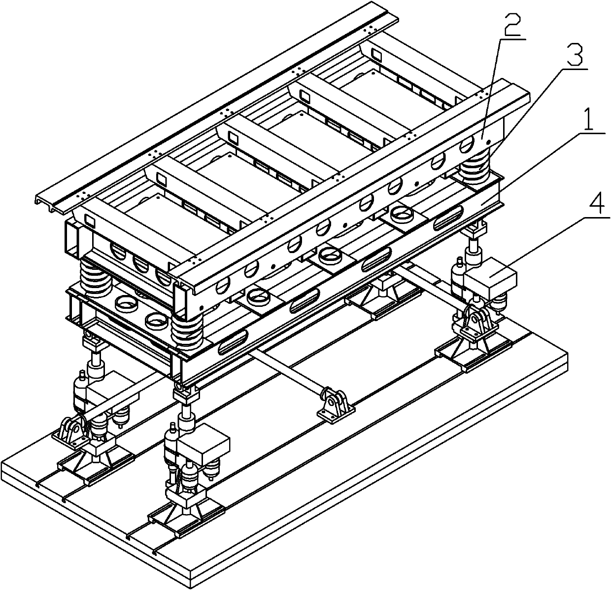
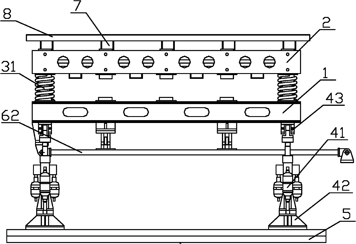
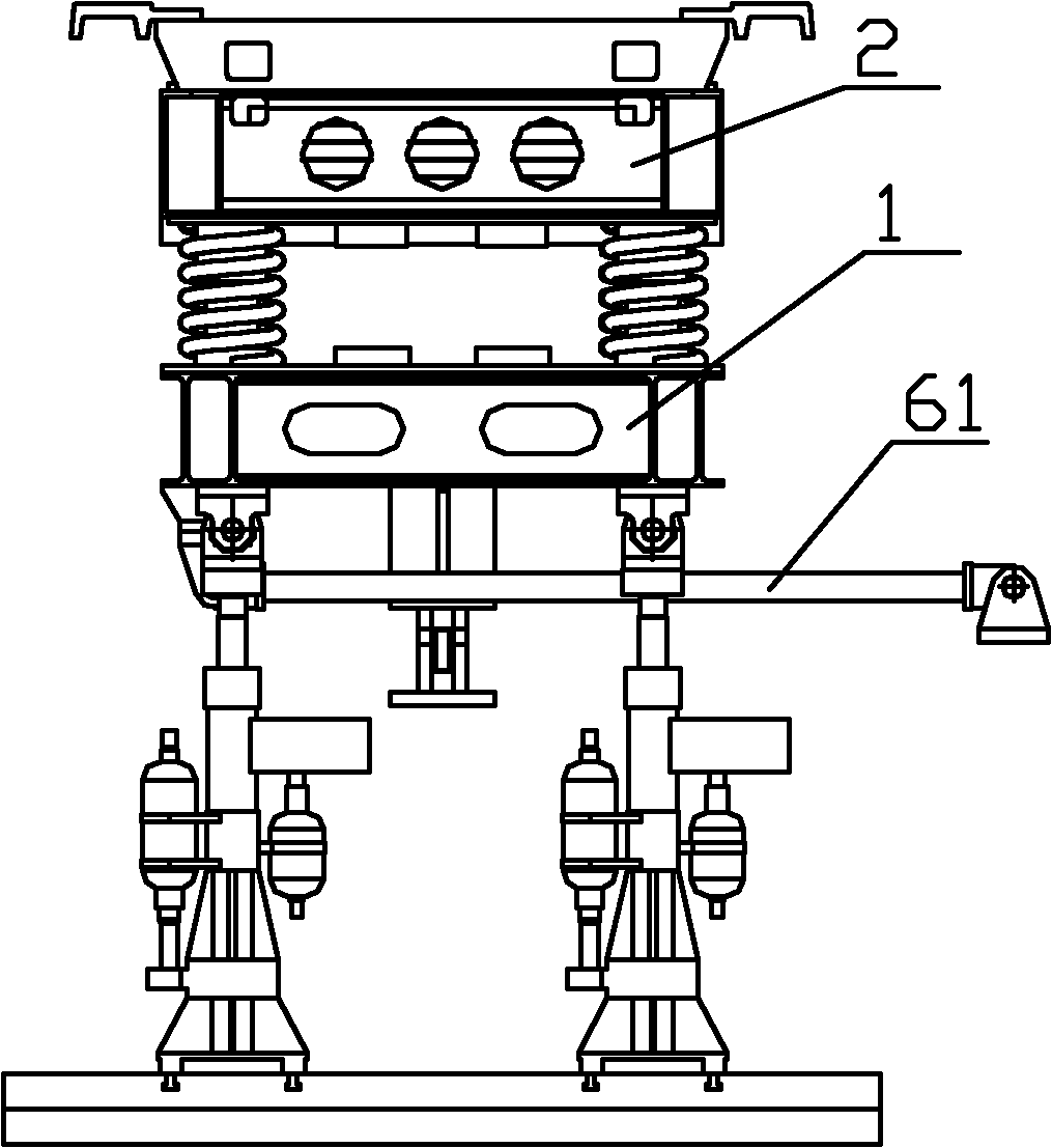
[0018] Take the F rail of the low-speed maglev train, the 14-point hydraulic support of the first-level platform, and the maximum 4×5 steel spring supports of the second-level platform 2 as an example.

[0019] Such as figure 1 , figure 2 , image 3 A maglev train electromechanical coupling vibration test device shown mainly consists of a hydraulic excitation system 4, a first-level platform 1 that simulates ground support, and a second-level platform 2 that simulates the quality of the track beam above the first-level platform 1. The track beam stiffness adjustment system 3 composed of adjusted steel springs and the horizontal displacement prevention auxi...


PUM


Abstract

The invention relates to the technical field of single levitation chassis testing for a maglev train, in particular to an electromechanical coupling vibration test device for the maglev train. The device comprises a primary platform for simulating ground support, a secondary platform which is positioned above the primary platform and simulates a track beam, and a track beam rigidity adjusting system for connecting the primary platform and the secondary platform, wherein the track beam rigidity adjusting system and the secondary platform supported by the track beam rigidity adjusting system form simulated maglev train track beam characteristics; and a hydraulic shock excitation system which applies excitation to the primary platform so as to simulate geometrical irregularity of track ground is fixed under the primary platform. The defects of the simplified single-point test or complete-vehicle debugging test for the conventional maglev train are overcome, the complex laboratory simulation of levitation control, elastic beam and coupling vibration environment of a levitation chassis mechanism for the maglev train is realized, the gap in research of key technology for domestic and overseas maglev trains is filled, and a scientific test means is provided for design of a levitation control system of the maglev train, the track beam characteristics and design of the mechanical structure of the levitation chassis.

Description

technical field [0001] The invention relates to the technical field of maglev train single-suspension frame testing, in particular to an electromechanical coupling vibration test device for maglev trains, which can simulate the suspension control-track beam-suspension frame machinery of high-speed and low-speed maglev trains and single-suspension frame of maglev trains with different gauges Structurally Coupled Vibration Environments. Background technique [0002] The suspension control system of the maglev train is a key technology. Due to the interaction force between the suspension control and the elastic track beam and the vehicle mechanical structure, the mechanical properties of the track beam and the suspension frame structure have a great influence on the suspension control effect of the maglev train. There is a significant impact. At present, there is no test device capable of simulating the "suspension control-elastic bridge-suspension frame mechanism coupling vib...

Claims


Application Information

Patent Timeline
IPC IPC(8): G01M7/02B06B1/18
Inventor 罗世辉马卫华梁鑫
Owner 常州西南交通大学轨道交通研究院
Learn More