
Total heat recovery humidifying fresh-air heat pump

A technology of total heat recovery and heat recovery, applied in heat recovery systems, space heating and ventilation, heating methods, etc., can solve the problems of high operating costs, increased cooling load, and small dehumidification, saving operating costs, reducing Dehumidification load, the effect of suitable outlet air temperature

Inactive Publication Date: 2011-03-30
帝思迈环境设备(上海)有限公司
View PDF9 Cites 77 Cited by
  • Summary
  • Abstract
  • Description
  • Claims
  • Application Information

AI Technical Summary

Problems solved by technology

[0002] The existing type of dehumidifier includes a refrigeration system composed of a compressor, a condenser, a throttling device, and an evaporator. The refrigeration principle is used to cool and dehumidify the air through the evaporator to absorb heat, and then all the condensers are used to heat the air to achieve dehumidification. The load is completely borne by the refrigeration system, the dehumidification capacity per unit of electric energy is small, the function is single, and all the condensation heat is used to heat the air, the temperature of the air outlet is high, and the cooling load is increased
[0003] Usually, the fresh air heat pump is in the fresh air mode, the operating cost is high, and the energy saving is not enough

Method used


Image

  • Total heat recovery humidifying fresh-air heat pump
  • Total heat recovery humidifying fresh-air heat pump
  • Total heat recovery humidifying fresh-air heat pump

Examples


Embodiment 1

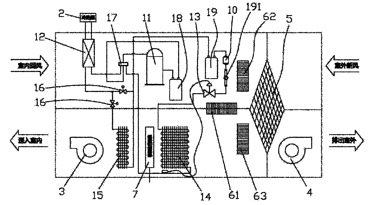
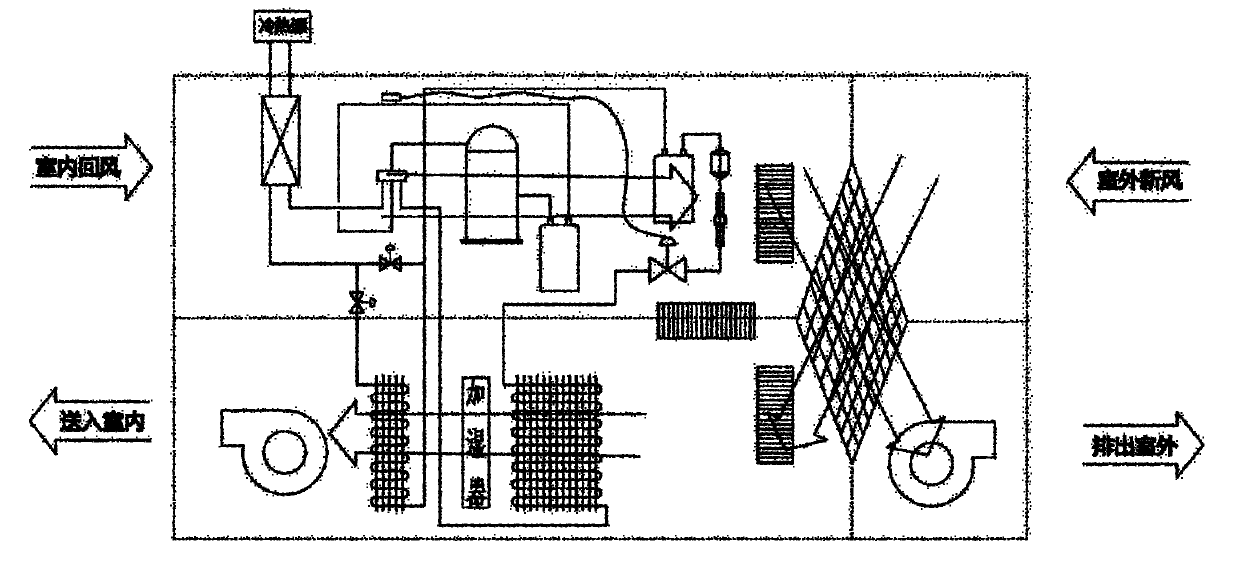
[0025] refer to Figure 1-4 : Humidity-adjusting fresh air heat pump with full heat recovery, including air inlet channel, exhaust air channel, refrigeration system, and central controller. Heater 12, throttling device 13, second heat exchanger 14 for cooling, dehumidifying or heating the fresh air, the second heat exchanger 14 is located in the air inlet channel, and the air blower 3 is arranged in the air inlet channel, An exhaust fan 4 is arranged in the air exhaust passage, and a heat recovery heat exchanger 5 for exchanging heat between fresh air and indoor return air is arranged between the inlet of the air inlet passage and the outlet of the exhaust air passage; the first heat exchange Between the device 12 and the throttling device 13, there is optionally connected a reheater 15 that can reheat the fresh air after cooling and dehumidification. The reheater 15 is located in the second heat exchanger in the air inlet channel along the flow direction of the fresh air. 14...

Embodiment 2

[0045] In this embodiment, the cold and heat source 2 is an air source heat pump, and air is used as the heat exchange source of the first heat exchanger 12 . Other structures and implementations of this embodiment are completely the same as those of Embodiment 1.


PUM


Abstract

The invention relates to a total heat recovery humidifying fresh-air heat pump comprising an air inlet channel, an air exhaust channel and a refrigeration system, wherein the refrigeration system comprises a compressor, a first heat exchanger, a throttling device and a second heat exchanger, wherein the first heat exchanger exchanges heat with cold and heat sources, the second heat exchanger is used for cooling, dehumidifying or heating fresh air, the second heat exchanger is positioned into the air inlet channel, an air blower is arranged in the air inlet channel, an exhauster is arranged in the air exhaust channel, a heat recovery heat exchanger which is used for exchanging the heat of the fresh air and indoor return air is arranged between an inlet of the air inlet channel and an outlet of the air exhaust channel, a reheater which is used for reheating the cooled and dehumidified fresh air is optionally connected between the first heat exchanger and the throttling device, and the reheater is positioned behind the second heat exchanger in the air inlet channel along the flow direction of the fresh air. The invention provides a humidifying fresh-air heat pump which is additionally provided with the heat exchangers to dehumidify, reheats air by the reheater, can select an air internal or external circulation mode according to the concentration of CO2, saves more energy and is simple to control.

Description

technical field [0001] The invention relates to a fresh air heat pump. Background technique [0002] The existing type of dehumidifier includes a refrigeration system composed of a compressor, a condenser, a throttling device, and an evaporator. The refrigeration principle is used to cool and dehumidify the air through the evaporator to absorb heat, and then all the condensers are used to heat the air to achieve dehumidification. The load is completely borne by the refrigeration system, the dehumidification capacity per unit of electric energy is small, the function is single, and all the condensation heat is used to heat the air, the temperature of the air outlet is high, and the cooling load is increased. [0003] Usually, the fresh air heat pump is in the fresh air mode, which has high operating costs and is not energy efficient enough. In fact, when the CO2 concentration of the indoor air is within a reasonable range of values, it is not necessary to provide fresh air, ...

Claims


Application Information

Patent Timeline
IPC IPC(8): F24F3/00F24F3/153F24F3/147F24F11/02
CPCY02B30/52Y02B30/123Y02P80/15
Inventor 林力健
Owner 帝思迈环境设备(上海)有限公司
Learn More