
Hydrofoil for water-borne vessels

A vehicle and hydrofoil technology, applied in the field of hydrofoils with trailing edges, can solve problems such as reduced rudder force and reduced working efficiency of hydrofoils, so as to increase hydrofoil resistance, improve fuel efficiency, and reduce the risk of damage Effect

Inactive Publication Date: 2011-03-30
BECKER MARINE SYST
View PDF6 Cites 9 Cited by
  • Summary
  • Abstract
  • Description
  • Claims
  • Application Information

AI Technical Summary

Problems solved by technology

[0006] Due to the formation of a Karman vortex street, on the one hand, the efficiency of the work of the hydrofoil is decreasing, that is, in the case of a rudder, the rudder force decreases

Method used


Image

  • Hydrofoil for water-borne vessels
  • Hydrofoil for water-borne vessels
  • Hydrofoil for water-borne vessels

Examples


Embodiment Construction

[0051] In the various embodiments of the present invention described below, the same components are provided with the same reference signs.

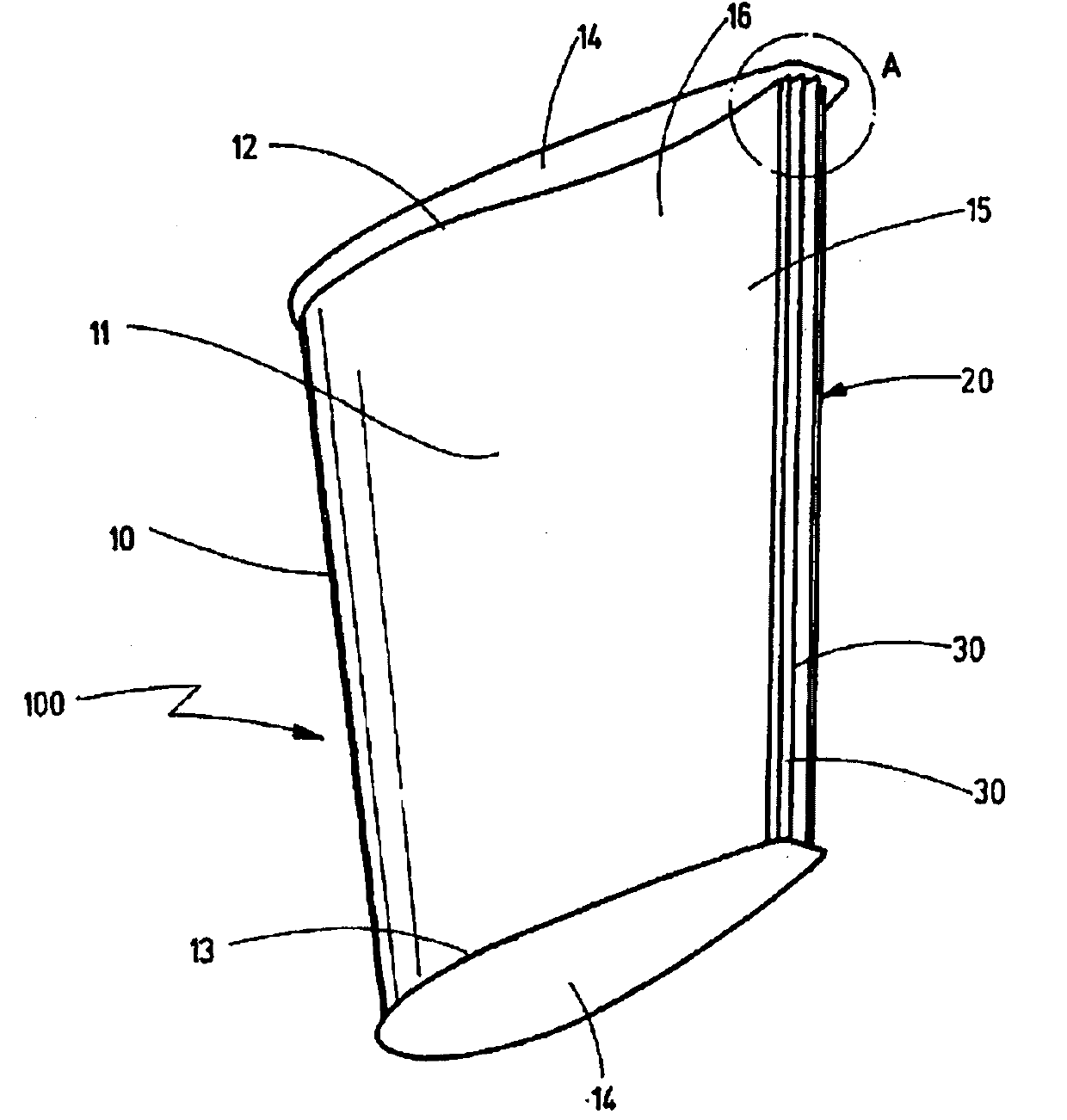
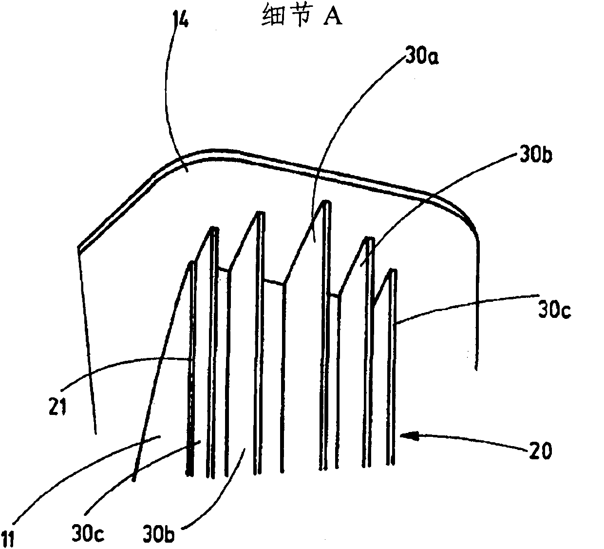
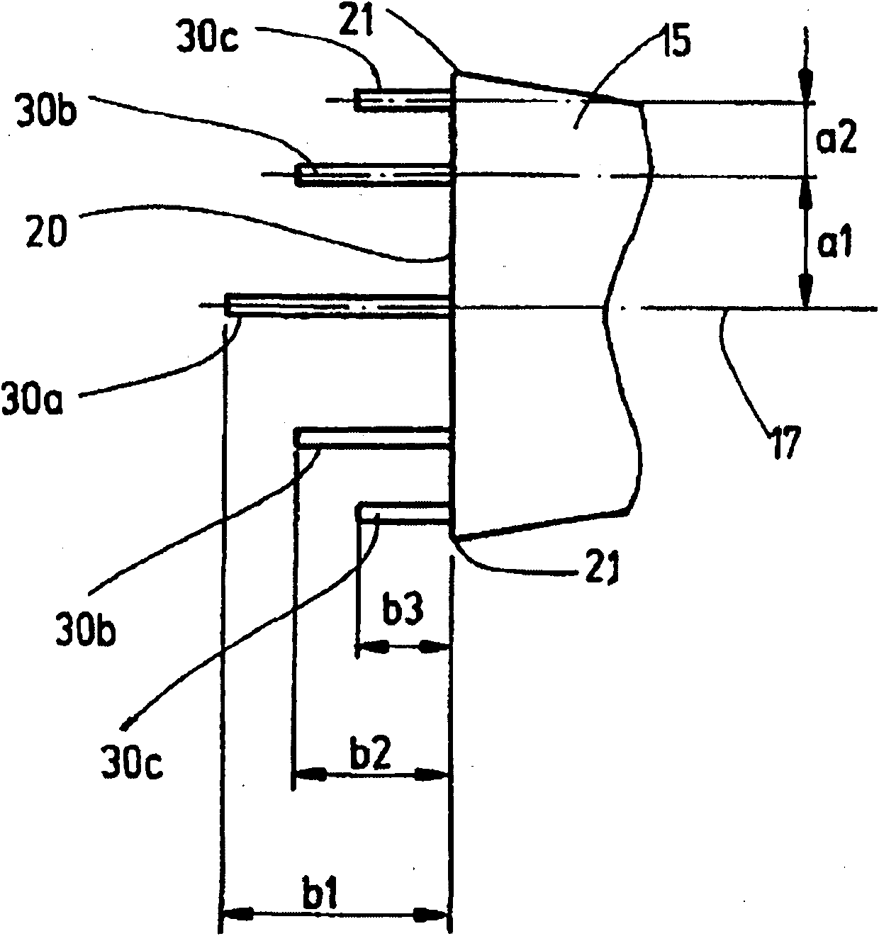
[0052] figure 1 A perspective view of the hydrofoil 100 is shown. In this case, the hydrofoil 100 has a fishtail shape or shilling (Schilling ) The shape of the rudder is formed. The rudder includes a leading edge 10 and a trailing edge 20. The side surface 11 extends between the leading edge 10 and the trailing edge 20. The end plates 14 are provided at the upper end 12 and the lower end 13 of the hydrofoil 100 in each case. Because the hydrofoil 100 adopts the form of a rudder with a fishtail shape, the end 15 of the rudder widens from the rear area 16 forming the narrowest part of the rudder to the trailing edge 20. A total of 5 protrusions 30 designed as plate-shaped ribs are provided at the trailing edge 20, which extend from the upper end 12 to the lower end 13 in each case and are arranged parallel to each other.

[0053] From ...


PUM


Abstract

Provided is a hydrofoil (100), in particular a rudder, for water- borne vessels, in particular ships, with a trailing edge (20), in which the negative effects of vortex formation in the direction of flow behind the hydrofoil, and / or of Karman vortex streets, are reduced, a projecting body (30) is arranged at the trailing edge (20) for the purpose of reducing vortex formation.

Description

Technical field [0001] The invention relates to a hydrofoil with a trailing edge, especially a rudder, used for water vehicles, especially ships. Background technique [0002] In the current context, a hydrofoil is a device used and / or installed in a water vehicle that generates buoyancy in the field of fluid mechanics. Examples of hydrofoils are rudder, spine, hydrofoil skid (Tragflügelkufen), stabilizer fins of water vehicles or other fin-shaped bodies on hydrofoil ships. The hydrofoil according to the present invention is particularly suitable for use as a rudder, wherein it is also possible to use it for one of the above-mentioned bodies, or for another hydrofoil type body. [0003] The hydrofoil in the known technology usually has a leading edge arranged in the direction of flow or in the direction of travel of the water vehicle, and a trailing edge opposite to the leading edge. The side or side wall of the hydrofoil is arranged between the leading edge and the trailing edge...

Claims


Application Information

Patent Timeline
Patent Type & Authority Applications(China)
IPC IPC(8): B63H25/38B63B1/24
CPCB63B39/06B63H25/38B63B1/248B63B41/00B63B3/38
Inventor 亨宁·库尔曼托马斯·法尔兹
Owner BECKER MARINE SYST
Learn More