
Pressure sensor for electric pressure cooker

A pressure sensor, electric pressure cooker technology, applied in pressure cookers and other directions, can solve the problem of not being able to transmit pressure signals to the control device, and achieve the effect of eliminating potential safety hazards and saving energy

Inactive Publication Date: 2011-03-30
乔林友
View PDF4 Cites 14 Cited by
  • Summary
  • Abstract
  • Description
  • Claims
  • Application Information

AI Technical Summary

Problems solved by technology

[0002] In the existing technology, a pressure cooker is equipped with a pressure limiting valve on the lid. When the pressure in the pot reaches a certain pressure, the pressure limiting valve will release the pressure to prevent the phenomenon of the pot from bursting, and the pressure signal in the pot cannot be transmitted to the control device.

Method used


Image

  • Pressure sensor for electric pressure cooker
  • Pressure sensor for electric pressure cooker

Examples


Embodiment Construction

[0011] The present invention will be further described below in conjunction with the accompanying drawings.

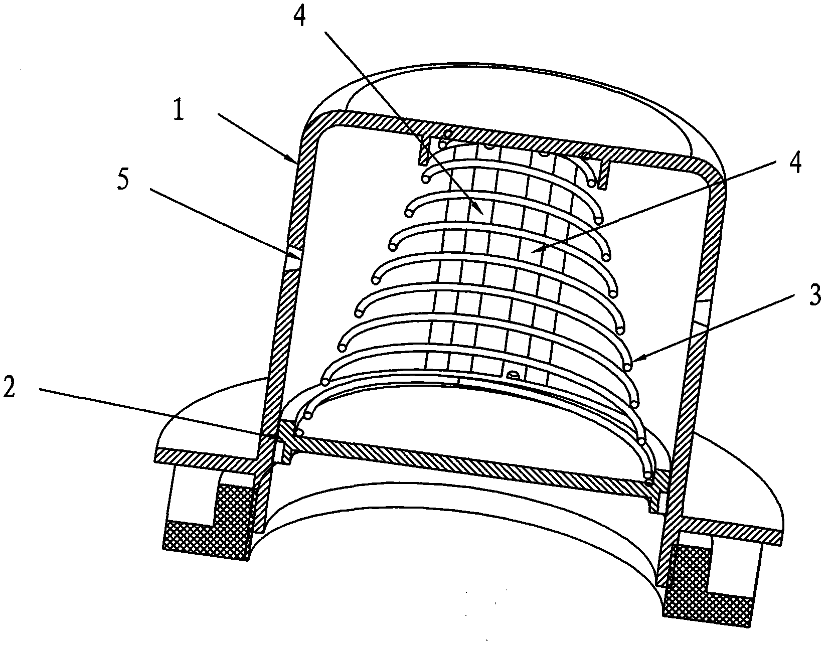
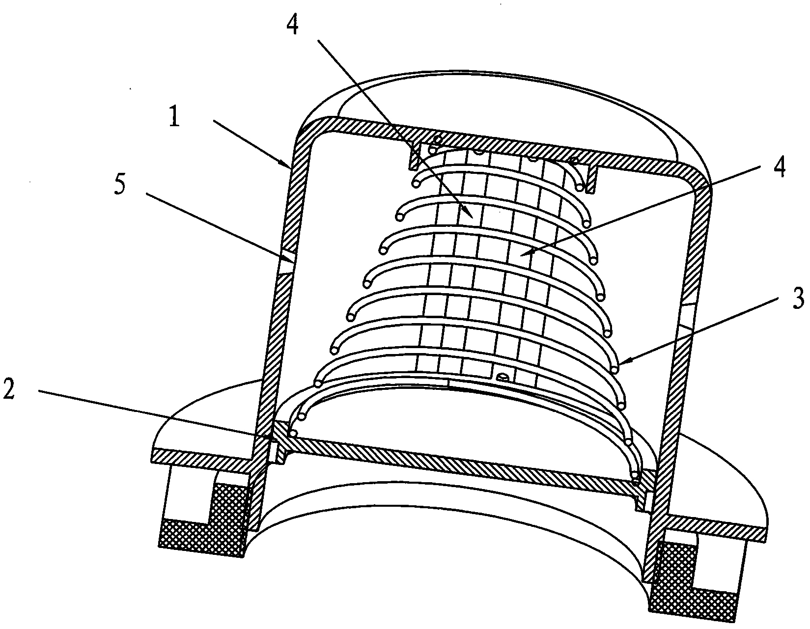
[0012] Such as figure 1 Shown, a kind of pressure sensor that electric pressure cooker is used, it comprises and has lower opening cylinder 1, piston 2, pressure spring 3 and potentiometer;

[0013] Piston 3 is slidingly matched with cylinder 1 and is liquid-gas sealed. One end of pressure spring 3 cooperates with piston 2, and the other end cooperates with the top plate of cylinder 1; piston 2 drives the potentiometer, and the cylinder between piston 2 and the top plate of cylinder 1 The wall has a limit pressure relief hole 5.

[0014] Described potentiometer comprises two resistive strips 4, and two resistive strips 4 are arranged in parallel in a row, and two resistive strips 4 are arranged in the cylinder barrel 1 parallel to the axis of the cylinder barrel, and the resistive strips 4 are insulated from the cylinder barrel 1, Piston 2 is used as the connection l...


PUM


Abstract

The invention relates to a pressure sensor for an electric pressure cooker, which comprises a cylinder barrel with a lower opening, a piston, a pressure spring and an a potentiometer, wherein the piston and the cylinder barrel are in sliding fit with each other and subjected to liquid-gas sealing; one end of the pressure spring is matched with the piston, and the other end of the pressure spring is matched with a top plate of the cylinder barrel; and the potentiometer is driven by the piston, and a limit pressure relief hole is formed on the cylinder barrel wall between the piston and the top plate of the cylinder barrel. Due to the adoption of the structure, when the pressure in the cooker ascends, the piston moves upwards, an electrical signal of a resistor is transmitted to a control device of the electric pressure cooker; and when the set pressure requirement is met, the control device is subjected to outage to stop heating and save energy, so even if the potentiometer is damaged and the limit pressure relief hole relieves pressure, the phenomenon of cooker explosion does not occur, and potential safety hazards are eliminated.

Description

technical field [0001] The invention relates to a device for an electric pressure cooker, in particular to a pressure sensor for the electric pressure cooker. Background technique [0002] In the current existing technology, a pressure cooker is equipped with a pressure limiting valve on the lid. When the pressure in the pot reaches a certain pressure, the pressure limiting valve will release the pressure to prevent the phenomenon of the pot from bursting, and the pressure signal in the pot cannot be transmitted to the control device. . Contents of the invention [0003] The purpose of the present invention is to provide a pressure sensor for an electric pressure cooker, which can transmit the pressure in the cooker to the control device through an electric signal, so as to prevent the cooker from bursting and eliminate potential safety hazards. [0004] The present invention is achieved as follows: a pressure sensor for an electric pressure cooker, which includes a cylin...

Claims


Application Information

Patent Timeline
IPC IPC(8): A47J27/09
Inventor 乔林友
Owner 乔林友
Learn More