Torsion detecting rim motor

A motor and rim technology, which is applied in the field of rim motors with torque detection, can solve the problems of large distance intervals, inability to accurately detect torque, and inability to assist in timely application of force, etc., to improve ease and ease of operation degree of effect

Inactive Publication Date: 2013-02-27
李宝玲
View PDF0 Cites 0 Cited by
  • Summary
  • Abstract
  • Description
  • Claims
  • Application Information

AI Technical Summary

Problems solved by technology

[0008] 2. The first and second magnetic assemblies B21 and C1 are provided on the adjacent sides of the four pushing seats B2 and fixing seats C. When the bicycle is started, it is necessary to step on the pedal to rotate more than 1 / 4 circle. The magnetic sensor will detect the magnitude of the torque and start the motor. If it is necessary to start the motor after averaging multiple detected torque values, it is necessary to step on the pedal and rotate for more than 1 / 2 circle. When the auxiliary power of the motor is most needed, the lack of timely auxiliary force cannot be provided, and the distance between the first and second magnetic components B21 and C1 is large, resulting in the inability to accurately detect the torque
[0009] The above-mentioned commonly used torque detection device has many problems and deficiencies, which is the goal that the inventors and those engaged in this industry want to improve.

Method used


Image

  • Torsion detecting rim motor
  • Torsion detecting rim motor
  • Torsion detecting rim motor

Examples


Embodiment 1

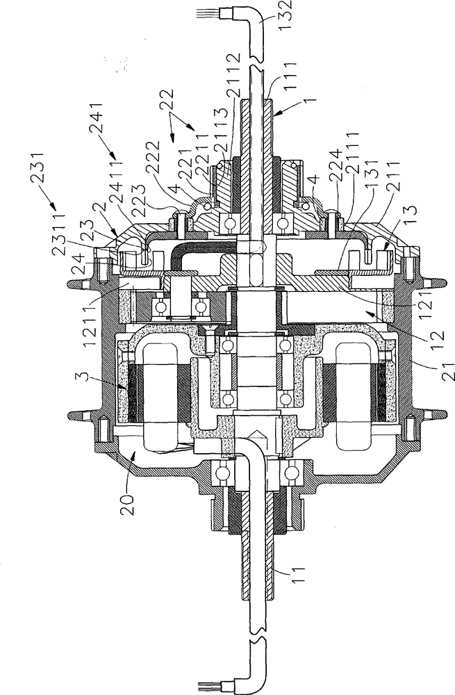
[0041] Such as figure 1 , figure 2 As shown, the present invention includes a fixed device 1, a movable device 2 driven by an external force to rotate the wheel, a power motor 3 that drives the movable device 2 to rotate, and an elastic component 4 linked by the movable device 2, wherein:

[0042] This immovable device 1 is installed on the vehicle 5, and the immobile device 1 is provided with a through groove 111 in the central shaft 11, and is provided with a reduction gear group 12 on the central shaft 11, and the reduction gear group 12 (the present invention) The reduction gear set is prior art) is a planetary gear set, including a sun gear, ring teeth and a plurality of planetary gears.

[0043] An accommodating space 20 is formed between the movable device 2 and the stationary device 1, and the movable device 2 is provided with a wheel shell 21 covering the outside of the stationary device 1 and connected to a wheel 51, one side of the wheel shell 21 A shell cover 2...

Embodiment 2

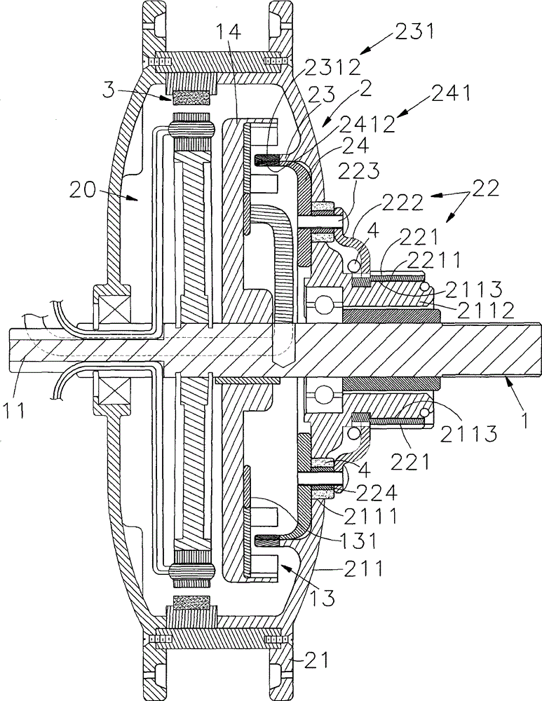
[0051] Such as image 3 As shown, the difference between this embodiment and Embodiment 1 is that the central shaft 11 of the immovable device 1 is fixed with a fixed frame 14, and the sensor 13 is installed on the fixed frame 14. In this way, the overall thickness of the rim motor 6 is reduced. Thinned. The driven rotating grid plate 23 of this embodiment and the first embodiment can be locked to the shell cover 211, and can also be integrally formed by the shell cover 211; moreover, the driven rotating grid plate 23 and the active rotating grid plate 24 can also be exchanged and stacked according to design requirements. Therefore, the active rotating grid plate 24 can also be locked on the shell cover 211 or made of integral molding of the shell cover 211, so that the driven rotating grid plate 23 does not Additional manufacturing and assembly are required, which not only reduces the overall thickness, but also saves manufacturing costs and assembly steps and time.

Embodiment 3

[0053] Such as Figure 4 , Image 6 , Figure 7 As shown, the fixed device 1 of this embodiment is the same as the embodiment 1. The movable device 2 includes a wheel shell 21 and a shell cover 211. One side of the wheel shell 21 is provided with a shell cover 211 for the elastic component 4 to resist. The moving module 22 includes a driven rotating disc 25 and a linking disc 222, one side of the linking disc 222 is opposite to the side of the case cover 211, and a connecting portion extending through the case cover 211 for the sprocket 26 to be fixed 2221, the active rotating grid plate 24 is fixed on the other side of the interlocking plate 222, and the sprocket 26 is located on the other side of the shell cover 211; A limiting groove 2211 is formed on the inner wall of the cover 211 , and the limiting block 2113 on the connecting portion 2221 is accommodated in the limiting groove 2211 . The interlocking plate 222 is provided with a plurality of pushing parts 2222 on the...


PUM


Abstract

The invention relates to a torsion measuring device, in particular to a torsion detecting rim motor, which comprises a fixed device, a movable device, a power motor and an elastic component, wherein the fixed device is arranged on a vehicle and is provided with a sensor; the movable device is sleeved on the fixed device and is connected with a wheel through a stock; a linked module for receiving an external force is arranged on one side of the stock, and a driven rotary gate disc of a plurality of first detected area is arranged on the other side of the stock; the linked module is provided with a driving rotary grate disc which are superposed with the driven rotary grate disc; a plurality of second detected areas are formed on the driving rotary grate disc; the power motor is sleeved on the fixed device and accommodated in the stock of the movable device for driving the movable device to rotate; and the two ends of the elastic component bears the forces applied by the stock of the movable device and the linked module. In the invention, the change between the detected areas can be detected, the power motor, according to data size, can be started to provide corresponding auxiliary power, and time difference is eliminated and the operation simplicity is improved.

Description

technical field [0001] The invention relates to a torque measuring device, in particular to a rim motor with torque detection. Background technique [0002] Electric bicycles are currently one of the most popular means of transportation, especially under the environmental trend that the concepts of environmental protection, energy saving and carbon reduction are generally deeply rooted in the hearts of the people, electric bicycles have gradually replaced bicycles and become the mainstream of light-duty means of transportation in the future; however , in the structure of the electric bicycle, the most important power source is the auxiliary transmission power source such as the electric motor, therefore, it is necessary to control the operation of this auxiliary transmission power source well, so that the electric bicycle can , to achieve the effect of man-vehicle integration, otherwise it will only increase the power consumption and increase the safety issues of personnel r...

Claims


Application Information

Patent Timeline
Patent Type & Authority Patents(China)
IPC IPC(8): B62M6/50H02K7/10H02K11/00B62M7/12A61G5/04H02K11/20
Inventor 李宝玲
Owner 李宝玲
Why Eureka
Try Eureka