Luminescence device

A light-emitting device and accommodating space technology, applied in the direction of lighting devices, light sources, components of lighting devices, etc., can solve problems such as replacement, personnel injury, and lamp tube fragmentation, achieve high brightness, strengthen structure, and avoid high voltage The effect of electric shock

Inactive Publication Date: 2011-03-23
AUSK OPTOELECTRONICS
View PDF0 Cites 0 Cited by
  • Summary
  • Abstract
  • Description
  • Claims
  • Application Information

AI Technical Summary

Problems solved by technology

[0004] When the hot-cathode fluorescent lamp 1 wants to achieve higher brightness, it can be made into a longer shape, for example, the extension length is twice as long, but in this case, the structural strength of the lamp tube will be greatly reduced, and the transportation process or assembly During the process, an accident occurred in which the lamp tube shattered, resulting in personal injury
[0005] In addition, the lighting devices used in most households are hot-cathode fluorescent tubes, but hot-cathode fluorescent tubes have disadvantages such as long warm-up time, short service life, difficult dimming, and inability to frequently turn off, while cold-cathode fluorescent tubes have the disadvantages of long service life. Advantages of long life, easy dimming and quick turn off
If the user wants to use CCFLs instead of HCFLs for lighting, the user cannot buy CCFLs from the market and replace them directly, which also causes troubles for users

Method used


Image

  • Luminescence device
  • Luminescence device
  • Luminescence device

Examples


Embodiment Construction

[0050] A light emitting device according to a preferred embodiment of the present invention will be described below with reference to related drawings.

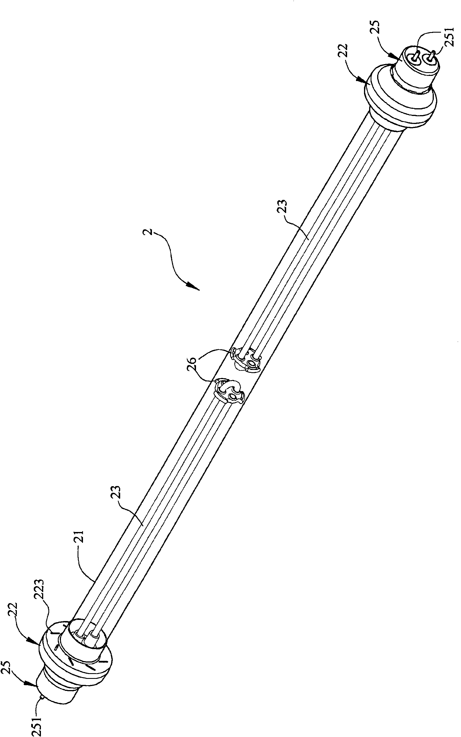
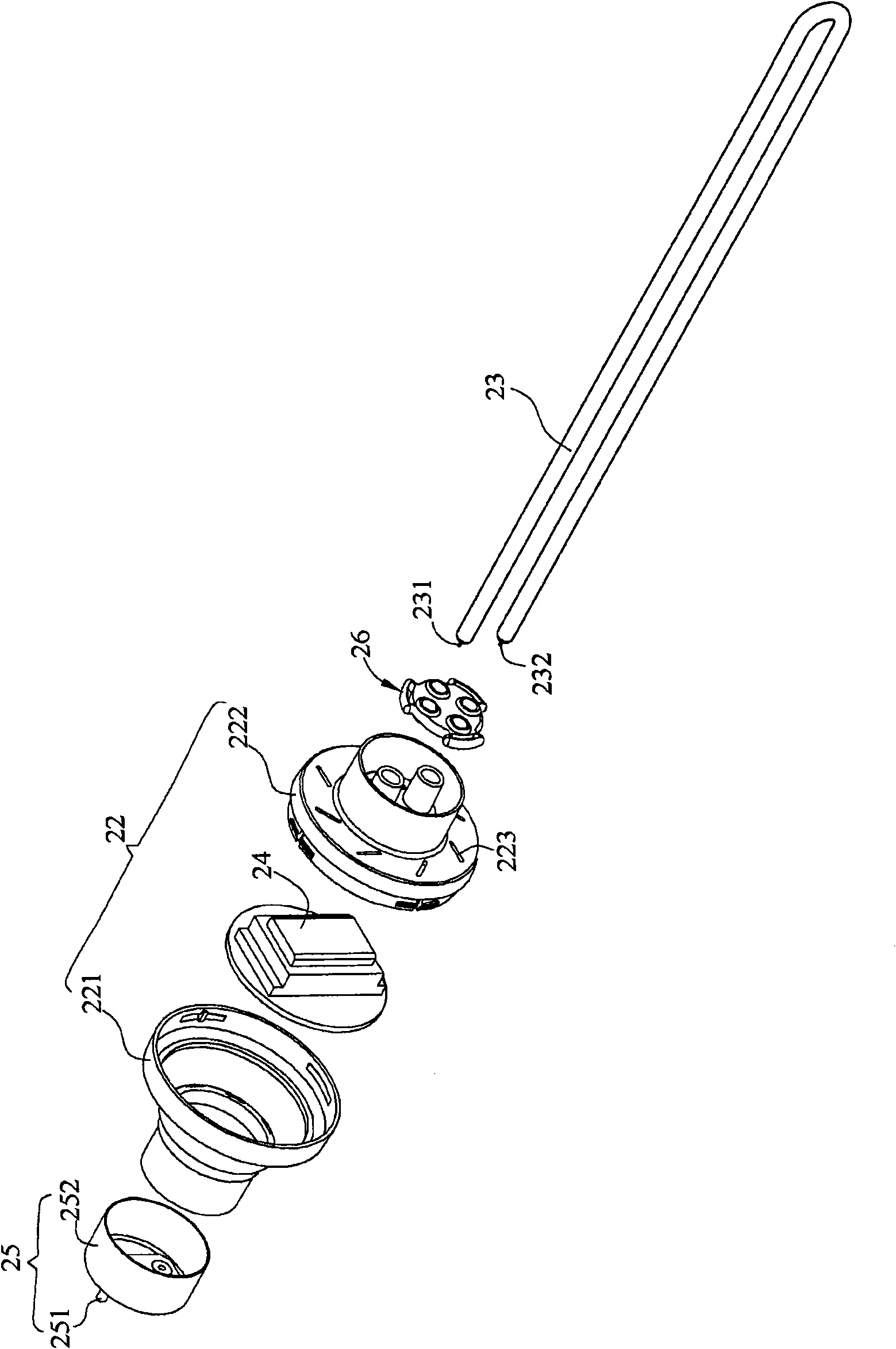
[0051] Please refer to figure 2 and image 3 A light emitting device 2 is shown to illustrate a preferred embodiment of the present invention. The lighting device 2 includes a tube body 21 , two casings 22 , two lamp tubes 23 and two inverters 24 . in, figure 2 is a combined schematic diagram of the light emitting device 2, image 3 It is an exploded schematic diagram of a part of the light emitting device 2 (which includes a casing 22, a lamp tube 23 and an inverter 24).

[0052] The light emitting device 2 can be used as an indoor or outdoor lighting device, an advertising billboard, a light box or a backlight module (such as a backlight module of a liquid crystal display device). In this embodiment, the light emitting device 2 is used as a lighting device as an example.

[0053] Please refer to figure 2 As shown, ...


PUM


Abstract

The invention relates to a luminescence device comprising a tube body, two shells, two lamp tubes and two current converters, wherein at least one part of the tube body transmits light; the shells are respectively arranged at the two opposite ends of the tube body and are linked with the tube body; each shell is respectively provided with a containing space; lamp tubes are contained in the tube body; and the current converters are respectively contained in each shell and are electrically connected with the lamp tubes. The luminescence device has the advantages that since the at least two lamp tubes are contained in the tube body, the lamp tubes are protected by the tube body so as to greatly strengthen the constitutive property; and the two lamp tubes can provide higher brightness.

Description

technical field [0001] The invention relates to a lighting device, in particular to a lighting device with a converter. Background technique [0002] With the development of the times, the light-emitting device has become one of the indispensable electrical appliances in people's daily life, and is applied in the fields of lighting and backlighting, for example. In the current technology, most light-emitting devices using fluorescent lamps as light sources may include hot cathode fluorescent lamps (Hot Cathode Fluorescent Lamp, HCFL) or cold cathode fluorescent lamps (Cold Cathode Fluorescent Lamp, CCFL). [0003] Hereinafter, a conventional hot cathode fluorescent lamp will be used for illustration. Please refer to figure 1 As shown, the HCFL tube 1 has a glass tube 11 , two filaments 12 and two lamp caps 13 . The glass tube 11 is filled with argon gas which is easy to discharge and a very small amount of mercury, and the inner wall of the glass tube 11 is coated with fl...

Claims


Application Information

Patent Timeline
Patent Type & Authority Applications(China)
IPC IPC(8): F21S2/00F21V15/02F21V19/00F21V23/00F21Y103/02
Inventor 林崇智
Owner AUSK OPTOELECTRONICS
Why Eureka
Try Eureka