
Multiaxial artificial joints tester

An artificial joint and testing machine technology, which is applied in the direction of testing wear resistance, etc., can solve the problems that the actual movement mode of the human hip joint is quite different, the artificial hip joint simulation testing machine has not yet been seen, and the structure is complex. Prevent leakage, good simulation effect

Inactive Publication Date: 2012-11-14
CHINA UNIV OF MINING & TECH
View PDF5 Cites 2 Cited by
  • Summary
  • Abstract
  • Description
  • Claims
  • Application Information

AI Technical Summary

Problems solved by technology

Among them, the pendulum shaft type mainly relies on the relative movement between the base and the inclined plane base to simulate the swing action of the hip joint in three different planes, which is an early testing machine; the pin-on-disk type friction and wear testing machine performs friction in the form of sliding contact. Wear test, through the relative motion formed between the disc and the test sample processed into a pin shape to study the friction performance of materials and the lubrication performance of synovial fluid, is currently a commonly used testing machine for artificial joint tribology. Although these two types of testing machines It can simulate the movement of the human hip joint, but the simulation method is quite different from the actual movement mode of the human hip joint
The multi-axis type mainly simulates the motion form of the artificial hip joint by synthesizing the individual motions formed by different shaft systems. Multi-axis artificial hip joint simulation test machine, etc., but its structure is complicated and the cost is high
At the same time, after various investigations and studies, it was found that there has been no relevant report on the development of this kind of artificial hip joint simulation test machine in China.

Method used


Image

  • Multiaxial artificial joints tester
  • Multiaxial artificial joints tester

Examples


Embodiment Construction

[0011] An embodiment of the present invention will be further described below in conjunction with accompanying drawing:

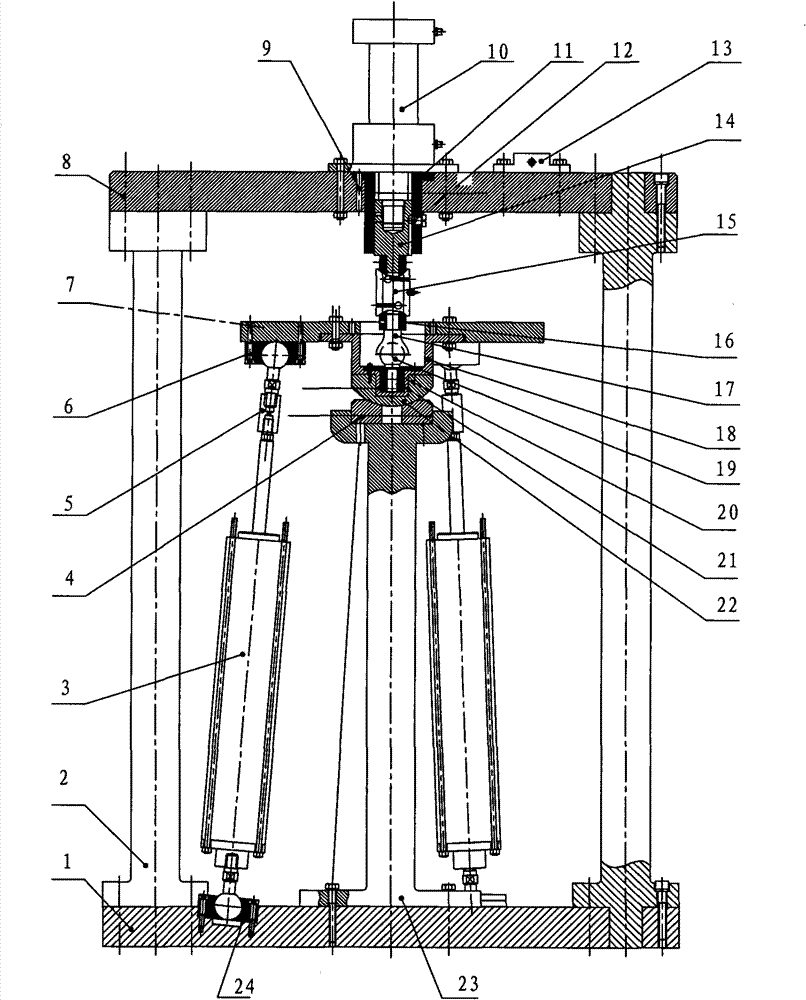
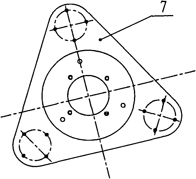
[0012] figure 1 As shown, the multi-axis artificial joint testing machine of the present invention is mainly composed of a frame-shaped support, an electric cylinder 3, a center support 23, a solution basin 18, a moving platform 7, an upper ball hinge 6, and a lower ball hinge 24. The frame-shaped support includes The top plate 8, the base plate 1 corresponding to the top plate 8, and a pillar 9 for fixing it as a whole by bolts is arranged between the top and bottom plates. The bottom plate 1 middle part of the frame-shaped support is fixed with a central support 23 through screws, and three reinforcing ribs are evenly arranged on the outside of the central support 23 in the longitudinal direction. There is a spherical base 22 matching its arc surface, and the middle part of the arc seat ring 4 has a through hole that helps the disassembly of the spherica...


PUM


Abstract

The invention discloses a multiaxial artificial joints tester, which comprises a timber frame. A central support, which is equipped with a cambered seat ring, is arranged at the middle of the timber frame. A spherical base, which is arranged on the cambered seat ring, is equipped with a solution basin. A ball cup is sleeved in the solution basin. A moving platform is fixed to the rim of the solution basin. A plurality of upper spherical hinges are disposed at the bottom of the moving platform. The bottom plate is equipped with a plurality of lower spherical hinges corresponding with the upperspherical hinges. A electric cylinder is obliquely connected between the upper spherical hinges and the lower spherical hinges. The cotyle matching the articular head is disposed above the ball cup. A guide block is disposed above the cotyle. A tension transducer is connected between the cotyle and the guide block. The guide block is disposed inside a guide sleeve. The guide sleeve is equipped with a hydraulic cylinder. The piston rod of the hydraulic cylinder is connected with the guide block. A heating device is disposed inside the solution basin. The top board is equipped with a temperature controller. The tester provided by the invention has the advantages of simple and compact structure, good simulation effect, convenient operation and low cost.

Description

technical field [0001] The invention relates to an artificial joint testing machine, in particular to a multi-axis artificial joint testing machine suitable for simulating the actual movement of human hip joints and performing friction and wear tests on artificial joint materials. Background technique [0002] As human society enters the aging stage, various joint diseases related to aging, such as femur fractures, arthritis and other diseases, will occur in large numbers, so the demand for artificial joints will also increase day by day. At present, about 30 million people in the world have been implanted with artificial joints, and the annual replacement volume is about 2 million. Artificial joints are subjected to severe stress in the body, such as artificial hip joints, which have to withstand about 3.6×10 6 Load shocks and abrasions that may be several times the weight of the human body. At the same time, because normal human bones are constantly adjusting their appea...

Claims


Application Information

Patent Timeline
Patent Type & Authority Patents(China)
IPC IPC(8): G01N3/56
Inventor 葛世荣程刚刘金龙陈烜
Owner CHINA UNIV OF MINING & TECH
Learn More