
Chaotic frequency measuring system and method in similar micro-photon source navigation system

A micro-photon and chaotic detection technology, which is used in radio wave measurement systems, satellite radio beacon positioning systems, measurement devices, etc., can solve the problems of difficult detection accuracy and low frequency of weak photon signals, and achieve enhancement of low signal-to-noise ratio signals. Detection ability, the effect of eliminating the influence of the calculation step factor

Inactive Publication Date: 2011-03-02
XIDIAN UNIV
View PDF5 Cites 10 Cited by
  • Summary
  • Abstract
  • Description
  • Claims
  • Application Information

AI Technical Summary

Problems solved by technology

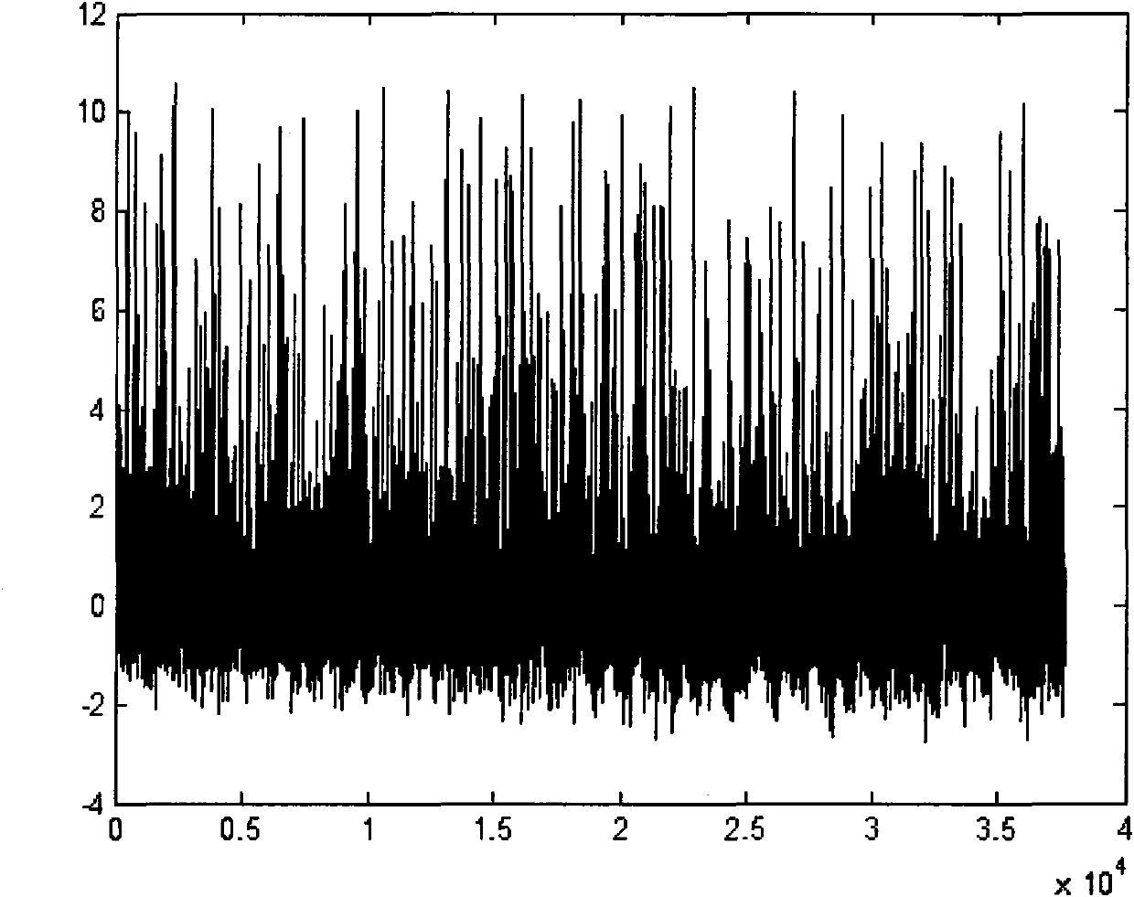
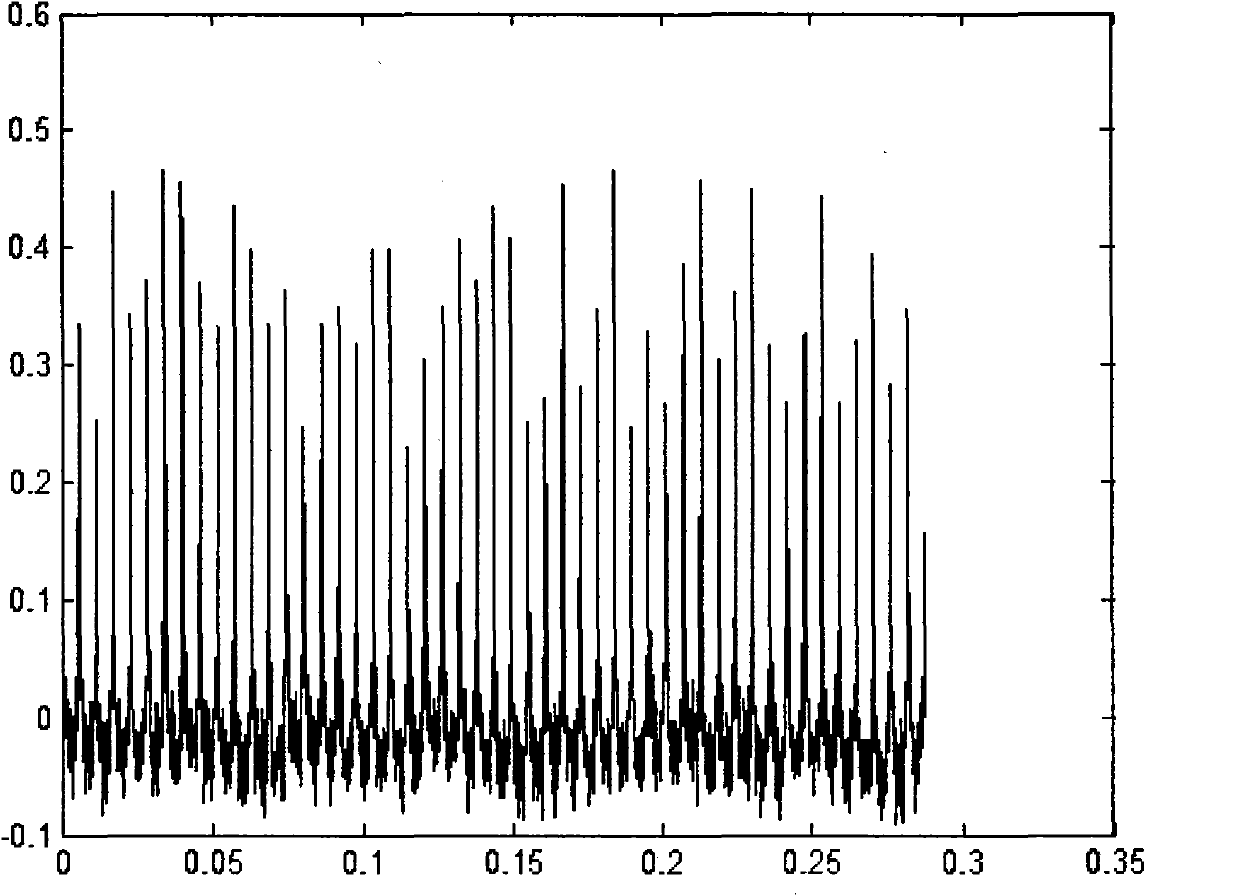
[0004] The purpose of the present invention is to solve the problem that the frequency of weak photon signals received by satellites is difficult to detect or the detection accuracy is not high in a class of advanced navigation (such as X-ray pulsars, quantum, etc.) systems, and proposes a similar microphoton source navigation system The chaotic frequency measurement system and method aim to provide high-precision frequency measurement for navigation signals, provide a new idea and new method for the research of advanced navigation key technologies, and facilitate the verification of advanced navigation theory methods and the application of engineering technology

Method used


Image

  • Chaotic frequency measuring system and method in similar micro-photon source navigation system
  • Chaotic frequency measuring system and method in similar micro-photon source navigation system
  • Chaotic frequency measuring system and method in similar micro-photon source navigation system

Examples


Embodiment Construction

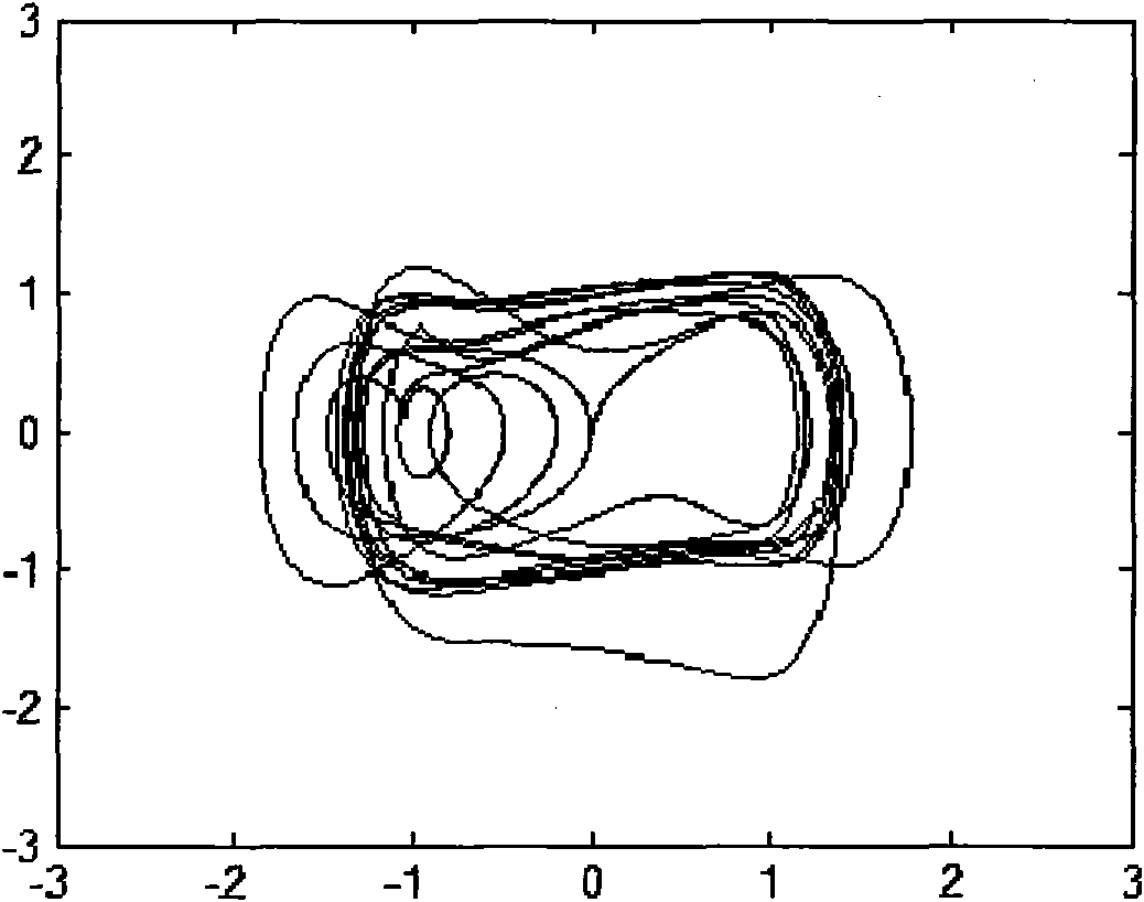
[0028] Such as figure 1 As shown, the present invention includes modules such as a photon detector, a sampling integrator, a chaos detector, a phase track analyzer, an evaluation unit, and a parameter setting unit. The photon detector detects the micro-photon signal from the navigation transmitter and sends it to the sampling integrator for pulse sampling integration to eliminate uncertain random interference. The pulse profile information obtained by sampling integration is input into the chaos detector as the signal to be detected. Different parameter configurations of the detector draw the phase trajectory plane, analyze the phase trajectory plane, determine the parameters of the chaotic detector when the phase trajectory plane transfers from the chaotic state to the large-period motion state, perform system parameter tuning, and evaluate the system performance index, and obtain The optimal chaotic system model and parameter configuration can be obtained, which can be appli...


PUM


Abstract

The invention discloses a chaotic frequency measuring system and a method in a similar micro-photon source navigation system, mainly solving the problems that low SNR micro-photon signal frequency in a similar photon source advanced navigation positioning and time synchronization system is hard to measure or has low measurement precision. The system is mainly composed of a photon detector, a sampling integrator, a chaos detector, a phase path analyzer, an evaluation unit, a parameter setting unit and other modules. The frequency measuring method of the invention comprises the following steps: inputting micro-photon pulse profile information obtained by sampling integration to a chaos detection model; analyzing the plane of the phase path to determine a critical chaos state parameter; obtaining a frequency parameter by a chaotic frequency measuring principle and a realization method; and carrying out evaluation. The invention has the characteristics that the low SNR micro-photon signal frequency can be accurately detected and recognized under the environment of strong noise. The invention can be used for measuring, calibrating and recognizing the signal resource frequency of advanced navigation systems, such as X-ray pulsar, quantum and the like, and can expand to application fields, such as radar multi-base signal reception, other SNR signal detection and the like.

Description

1. Technical field [0001] The invention belongs to the technical field of satellite navigation timing positioning, and relates to a chaotic frequency measurement system and method for navigation positioning and time synchronization using a weak photon signal source in an advanced navigation system. The system measures the system photon signal frequency based on a chaotic dynamics model , which aims to provide high-precision frequency calibration and time measurement for navigation signals similar to micro-photon sources. It can detect parameters such as frequency and period of photon sources, and can be used to evaluate system signal performance. At the same time, the present invention can also be expanded and applied to the identification of photon source signals. 2. Background technology [0002] As the signal source of the new satellite navigation and positioning system, the weak photon pulse signal has been applied in the research and practice of a class of advanced navi...

Claims


Application Information

Patent Timeline
IPC IPC(8): G01R23/02G01S19/35G01S7/48
Inventor 王勇许录平乔鑫苏哲张华
Owner XIDIAN UNIV
Learn More