Oil pressure coating device
A coating machine and oil pressure technology, applied in the direction of spraying devices, liquid spraying devices, etc., can solve the problems of paint viscosity reduction, environmental adverse effects, and adhesion decline, etc., achieve low dust storms, superior stability, and reduce the cost of the work site Effect
- Summary
- Abstract
- Description
- Claims
- Application Information
AI Technical Summary
Problems solved by technology
Method used
Image
Examples
Embodiment Construction
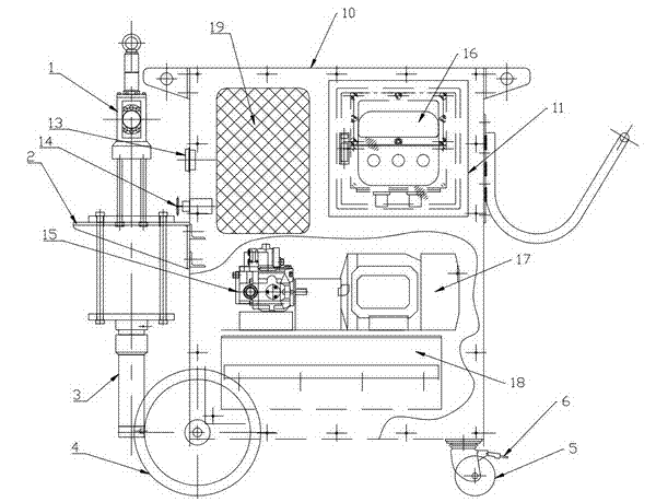
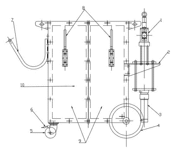
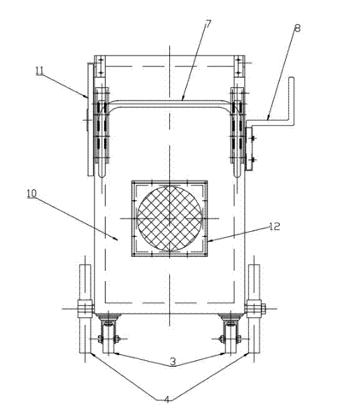
[0013] Figure 1 to Figure 6 The reference signs shown are as follows: hydraulic cylinder 1, fixed table 2, painting pump part 3, rubber wheel 4, small wheel 5, automatic brake 6, painting hose storage area 7, power cable storage area 8, Main box door 9, main box 10, observation window 11, exhaust port 12, discharge oil pressure gauge 13, pressure regulator gauge 14, piston pump 15, pressure-resistant explosion-proof brake disc 16, electric motor 17, fuel tank 18, fuel filler 18.1, oil suction filter 18.2, hydraulic gauge 18.3, suction port 19.
[0014] Figure 1 to Figure 6 In the schematic diagram of a hydraulic coating machine shown, its main structural features are: it consists of a main chassis 10, a hydraulic device, a spraying device, a mobile device, and a spray gun, and also includes a fixed table 2, a coating pump part 3, and a rubber Wheel 4, small wheel 5, automatic brake 6, paint hose storage area 7, power cable storage area 8, piston pump 15, pressure-resistant...
PUM
 Abstract
Description
Claims
Application Information
 - R&D
- Intellectual Property
- Life Sciences
- Materials
- Tech Scout
- Unparalleled Data Quality
- Higher Quality Content
- 60% Fewer Hallucinations
Browse by: Latest US Patents, China's latest patents, Technical Efficacy Thesaurus, Application Domain, Technology Topic, Popular Technical Reports.
© 2025 PatSnap. All rights reserved.Legal|Privacy policy|Modern Slavery Act Transparency Statement|Sitemap|About US| Contact US: help@patsnap.com


