Seatbelt retractor

A seat belt retractor and webbing technology, which is applied in the direction of seat belts, belt retractors, transportation and packaging, etc. in the car, and can solve the problem of the limit of the size of the thickened end.

Inactive Publication Date: 2011-02-23
ASHIMORI INDS
View PDF1 Cites 2 Cited by
  • Summary
  • Abstract
  • Description
  • Claims
  • Application Information

AI Technical Summary

Problems solved by technology

In the forging process, the extent to which the dimensions of the ends can be thickened in a single step is limited

Method used


Image

  • Seatbelt retractor
  • Seatbelt retractor
  • Seatbelt retractor

Examples


Embodiment Construction

[0064] Hereinafter, an embodiment of a seat belt retractor according to the present invention will be described in detail with reference to the accompanying drawings.

[0065] rough structure

[0066] First, based on figure 1 and figure 2 A schematic structure of the seat belt retractor 1 according to the present embodiment will be described.

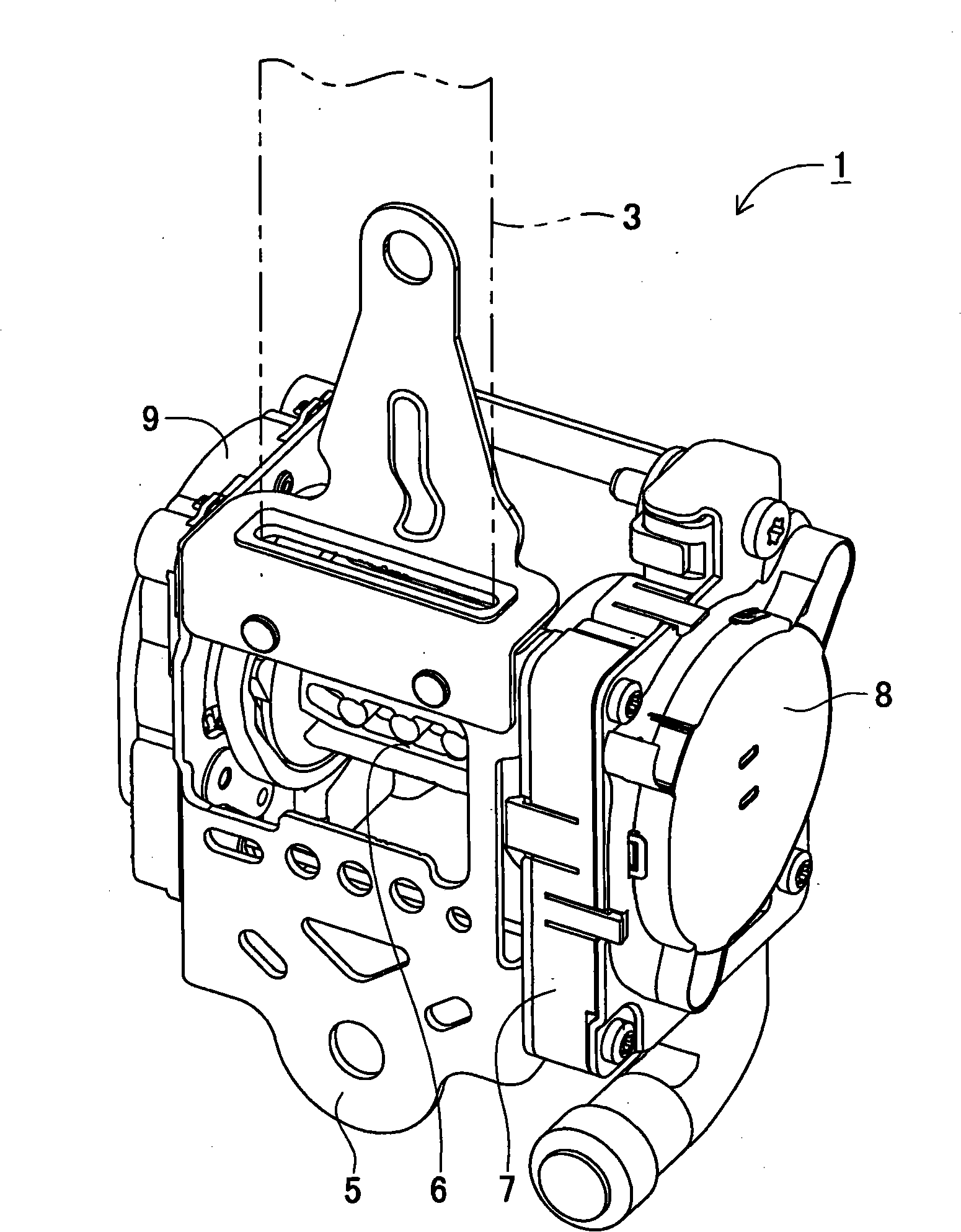
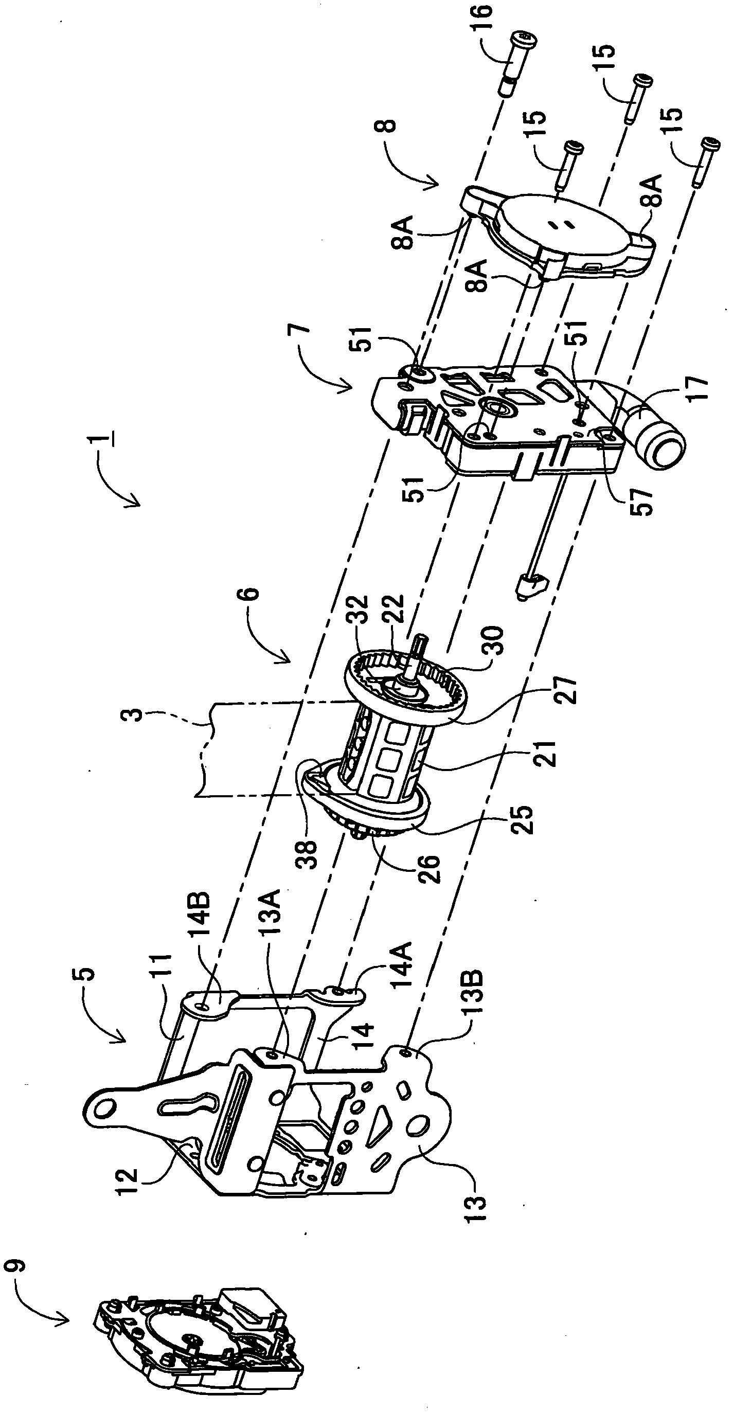
[0067] figure 1 It is a perspective view showing the appearance of the seat belt retractor according to this embodiment. figure 2 It is a perspective view showing each component of the seat belt retractor 1 in a disassembled state.

[0068] like figure 1 and figure 2 As shown, the seat belt retractor 1 is a device for retracting a vehicle webbing 3 . The seat belt retractor 1 is composed of a housing unit 5 , a take-up drum unit 6 , a pretensioner unit 7 , a take-up spring unit 8 and a lock unit 9 .

[0069] The locking unit 9 is fixed to a side wall portion 12 of a housing 11 constituting a housing unit 5 to be described l...


PUM


Abstract

A seatbelt retractor includes a torsion bar (23) which is twisted and deformed depending on a load in a webbing-pull-out direction in case of vehicle collision. One end of the torsion bar is housed in a cylindrical hollow portion which is a hollow extending from an opening provided at an one-end side of a take-up drum (21) to an other-end side thereof co-axialIy to an axis of rotation, and via a first coupling member (23C), coupled with a concave coupling portion provided on an inner wall surface of the other-end side of the take-up drum with relative rotation of the torsion bar and the take-up drum being disabled.

Description

technical field [0001] The present invention relates to a seat belt retractor for restraining a vehicle occupant by means of a webbing to ensure the safety of the occupant. More particularly, the present invention relates to a so-called energy absorbing mechanism in which the webbing is effectively pulled out when resistance is applied to the webbing, thereby relieving impact forces on the vehicle occupant resulting from the movement of the vehicle occupant against the restraint of the webbing And the vehicle occupant is prevented from receiving an impact force exceeding a predetermined value. Background technique [0002] Conventionally, an energy absorbing mechanism employing a torsion bar is known. In this energy absorbing mechanism, the torsion bar is twisted with plastic deformation, so that the webbing is pulled out with a predetermined tension. [0003] Typically, torsion bars are formed by forging a round bar of steel. More specifically, a torsion bar is a torsion...

Claims


Application Information

Patent Timeline
Patent Type & Authority Applications(China)
IPC IPC(8): B60R22/46
CPCB60R22/4633B60R2022/287B60R22/4676
Inventor 林静奈片山贵夫
Owner ASHIMORI INDS
Why Eureka
Try Eureka