Anti-receiver phase jump method for measuring directions of interference sources
A phase hopping and receiver technology, which is applied in directions such as direction finders and radio wave director components using radio waves, and can solve problems such as high requirements for consistency, large influence of phase hopping direction finding accuracy, and performance degradation. , to achieve the effect of solving performance degradation, reducing work difficulty, and reducing high consistency requirements
- Summary
- Abstract
- Description
- Claims
- Application Information
AI Technical Summary
Problems solved by technology
Method used
Image
Examples
Embodiment 1
[0024] Embodiment 1: This embodiment adopts a circular array of 5 array elements in the ultrashort wave frequency band, and performs a simulation experiment in the case of two interference sources; its specific steps are as follows:
[0025] A. Set up a sparse dictionary:
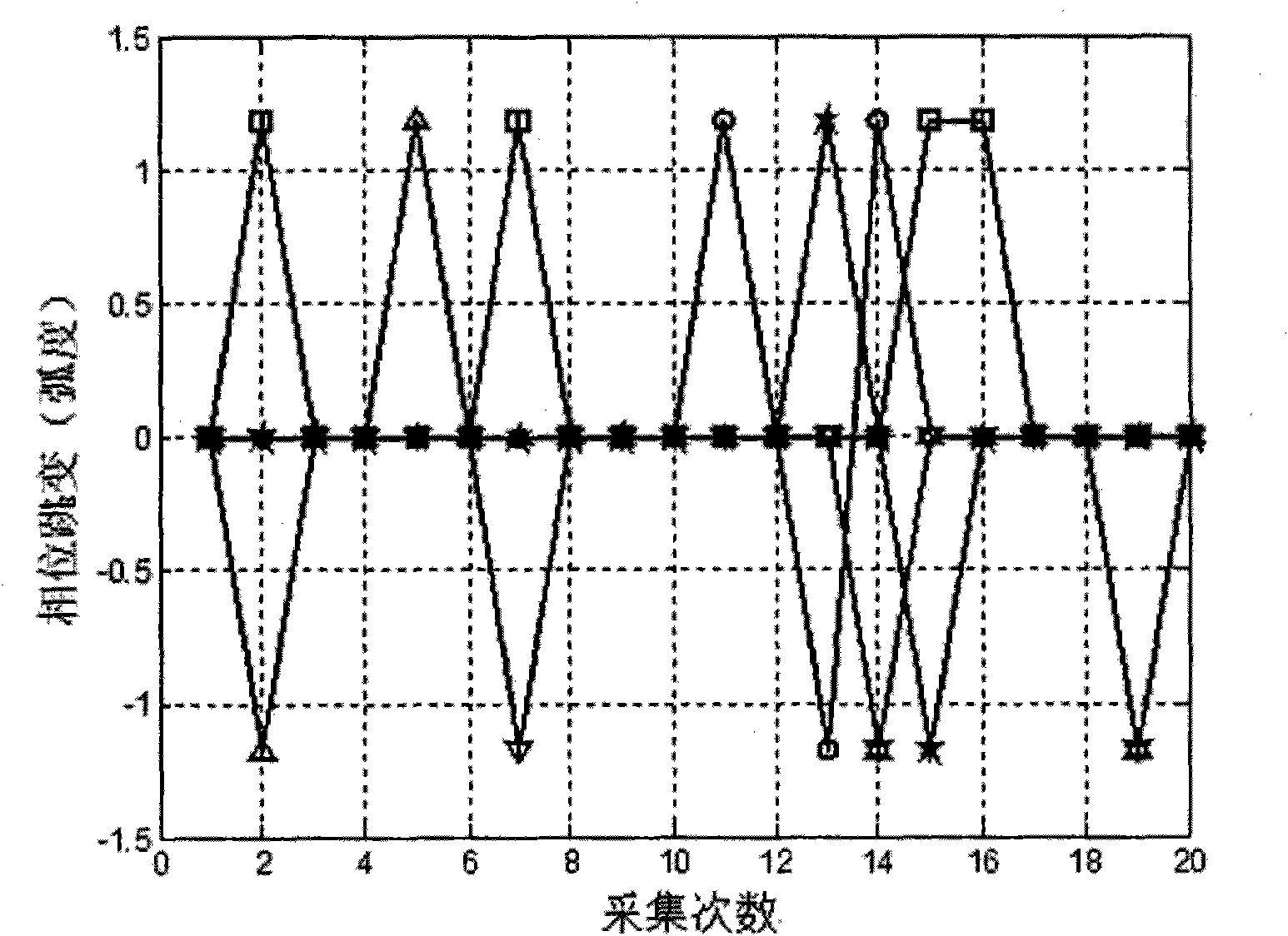
[0026] A 1 .Initial setting of receiver operating parameters: the operating frequency of the interference source is set to f c =320MHz; the system sampling frequency is set to f s = 40.96MHz; array element radius r = 0.75m; interference source signal-to-noise ratio is set to SNR = 20dB; number of acquisitions P = 20 times; interference source type and number: 2 coherent signals, respectively S 1 (t), S 2 (t), the direction of arrival of the two interference sources is set to 40° and 250° respectively; it is simulated by Gaussian white noise with zero mean and standard deviation of 1, and the corresponding collected data is denoted as S 1 (k), S 2 (k); The two hopping modes are respectively set as: no (...
Embodiment 2
[0060] In this embodiment, it is still assumed that there are two interference sources with incoming wave directions of 40° and 70°, and the rest of the parameters are the same as the parameter settings in Embodiment 1. The method of the present invention and the MUSIC method are used to perform simulation experiments respectively:
[0061] The simulation effect curve of this embodiment is as attached image 3 shown; attached Figure 4 Under the same conditions, the traditional MUSIC method simulates the effect curve; in the latter case, because the two interference sources have similar directions of arrival in the case of phase jump, a single spectral peak appears and the specific direction of arrival of the two interference sources cannot be distinguished; and In this embodiment, the directions of incoming waves of the two interference sources are clearly pointed out.
PUM
 Abstract
Description
Claims
Application Information
 - Generate Ideas
- Intellectual Property
- Life Sciences
- Materials
- Tech Scout
- Unparalleled Data Quality
- Higher Quality Content
- 60% Fewer Hallucinations
Browse by: Latest US Patents, China's latest patents, Technical Efficacy Thesaurus, Application Domain, Technology Topic, Popular Technical Reports.
© 2025 PatSnap. All rights reserved.Legal|Privacy policy|Modern Slavery Act Transparency Statement|Sitemap|About US| Contact US: help@patsnap.com


