
Mobile emergency power supply based on system converter

A technology of emergency power supply and converter, applied in emergency power supply arrangement, control/regulation system, conversion of AC power input to DC power output, etc., can solve the impact of short service life, few output interfaces, system capacity, battery volume and cost big problem

Inactive Publication Date: 2011-02-16
SHANGHAI JIAO TONG UNIV
View PDF4 Cites 23 Cited by
  • Summary
  • Abstract
  • Description
  • Claims
  • Application Information

AI Technical Summary

Problems solved by technology

[0006] After searching the prior art documents, it was found that A New Type of Three-phase Emergency Power Supply (EPS) (a three-phase emergency power supply (EPS)) design published by Guiyin Yu at the The Ninth International Conference on Electronic Measurement & Instruments academic conference An emergency power supply system based on the IPM module and DSPTMS320LF2407A processor is developed to realize the basic functions of the emergency power supply, but it has the following disadvantages: 1) The main circuit has a single source of electric energy, and only the battery is the only energy storage link. The phase bridge inverter circuit is output, and the battery has a short service life and high cost under frequent charge and discharge conditions, and the system capacity is greatly affected by the volume and cost of the battery
2) There is no reserved interface for new energy sources such as wind energy and solar energy, and it is impossible to use wind power generators and solar panels to output electric energy
3) There are few output interfaces, only one three-phase AC output can be output
4) The scope of application is small, and the emergency power system described in the literature is not movable, so it cannot be applied to occasions such as power rescue, communication maintenance, emergency handling, emergency rescue and disaster relief, etc.

Method used


Image

  • Mobile emergency power supply based on system converter
  • Mobile emergency power supply based on system converter
  • Mobile emergency power supply based on system converter

Examples


Embodiment Construction

[0044] The embodiments of the present invention are described in detail below. This embodiment is implemented on the premise of the technical solution of the present invention, and detailed implementation methods and specific operating procedures are provided, but the protection scope of the present invention is not limited to the following implementation example.

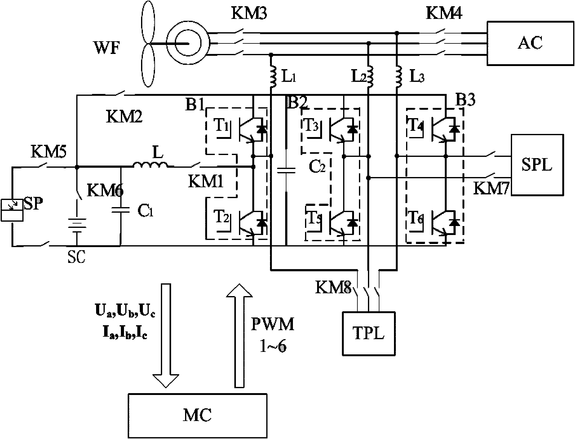
[0045] like figure 1 As shown, this embodiment includes: a battery module, a multi-functional converter, a DC reactor, three AC reactors, two DC stabilizing capacitors, eight contactors and a main control circuit module. Among them: the first contactor KM1 is connected to the middle point of the DC reactor L and the first bridge arm B1 of the multi-function converter module, and the battery module SC is connected to the DC power supply through the sixth contactor KM6 and the first DC stabilizing capacitor C1 in parallel. At the other end of the reactor L, the second DC capacitor C2 is connected in parallel to the ...


PUM


Abstract

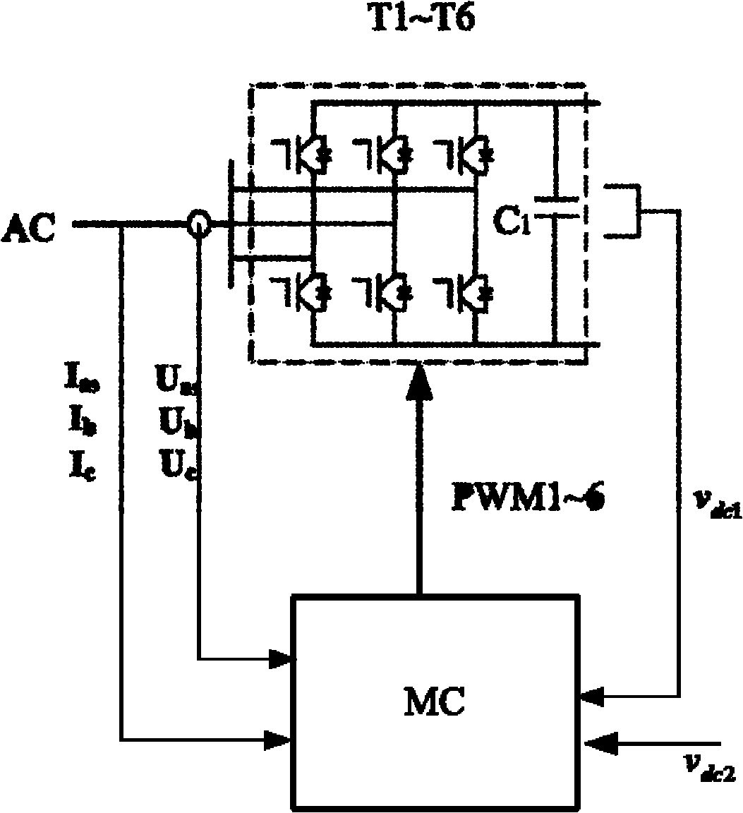
The invention relates to a mobile emergency power supply based on a system converter in the technical field of power supplies, which comprises a battery module, the multi-functional converter, a direct current reactor, three alternating current reactors, two direct current voltage-stabilizing capacitors, eight contactors and a main control circuit module. A DSP2812 digital signal processor is used as a core controller, a touch screen is adopted as a system upper computer, the running state of a system is selected, a running command signal of the system is given out, and the operation is simple. The core part of the power supply is the multi-functional converter, and the system can work in one state of direct current conversion, PWM rectification and PWM inversion by leading the contactorsto close different loops. Electrical energy can be derived from four inputs of wind energy, solar energy, commercial power and a diesel engine, thereby effectively improving the reliability of the system.

Description

technical field [0001] The invention relates to a device in the field of electric power supply technology, in particular to a mobile emergency power supply based on a system converter. Background technique [0002] Mobile emergency power supply has been widely used in various industries, such as backup power supply for modern buildings, emergency power supply in emergency rescue and disaster relief, medical treatment, fire fighting, military equipment, etc., and the demand continues to increase. In recent years, with the introduction of the micro-grid concept and the continuous development of distributed power generation systems, mobile emergency power supplies can also be used as backup support for small power grids, and as a grid-connected intermediary for various new energy sources. [0003] The mobile emergency power supply is based on fully controlled power electronic device IGBT and PWM conversion technology. Compared with the traditional mobile emergency power supply ...

Claims


Application Information

Patent Timeline
IPC IPC(8): H02M3/155H02M7/537H02M7/217H02J7/00H02J9/00
CPCY02E10/766Y02E10/76
Inventor 吴杰王志新
Owner SHANGHAI JIAO TONG UNIV
Learn More