
Light source module and preparation method thereof

A light source module, light emitting diode technology, applied in the direction of light source, electric light source, point light source, etc., can solve the problems of wire breakage, unprotected wire bonding, difficult mounting, etc., and reduce the probability of wire breakage , stable performance, easy to combine

Inactive Publication Date: 2011-02-16
DONGGUAN WANFENG NANOMETER MATERIALS
View PDF7 Cites 9 Cited by
  • Summary
  • Abstract
  • Description
  • Claims
  • Application Information

AI Technical Summary

Problems solved by technology

From the structural point of view, the welding wire of this solution is not protected and directly exposed to oxygen, and it is easy to oxidize when the temperature rises, causing disconnection; from the process point of view, the ordinary PCB board is hard and rigid, and it is difficult to mount and not firm. , when there is looseness, it is also easy to cause the welding wire to be broken, and there is a broken wire

Method used


Image

  • Light source module and preparation method thereof
  • Light source module and preparation method thereof
  • Light source module and preparation method thereof

Examples


Embodiment Construction

[0027] The present invention will be described in further detail below in conjunction with the accompanying drawings.

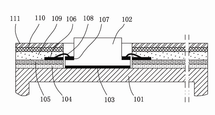
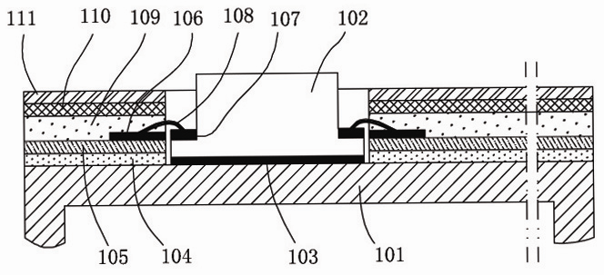
[0028] refer to figure 1 , the first embodiment of the present invention is a light source module, including a light emitting diode 102, and also includes a metal heat sink 101, the light emitting diode 102 is directly arranged on the metal heat sink 101 by SMT; the light source module also includes a flexible circuit board 105, the front side of the flexible circuit board 105 has a printed circuit 106, and the back side of the flexible circuit board 105 is attached to the metal heat sink 101 by PAS glue, that is figure 1The film layer shown in 104 in; the flexible circuit board 105 has a through hole, and the light emitting diode 102 is arranged in the through hole; One of the differences of the light-emitting diodes is that the connection end between the internal circuit and the external circuit is the electrode to be welded instead of the pin, and the ele...


PUM


Abstract

The invention relates to a semiconductor lighting technique, in particular to a light source module and a preparation method thereof. The light source module comprises a light emitting diode, a metal heating panel and a flexible circuit board, wherein the light emitting diode is directly arranged on the metal heating panel through an SMT (Surface Mounting Technology) mode; the obverse side of the flexible circuit board is provided with a printed circuit, and the reverse side of the flexible circuit board is pasted on the metal heating panel through PAS glue. The invention provides the light source module with the advantages of good heat dissipation effect and stable performance and the preparation method thereof.

Description

technical field [0001] The invention relates to semiconductor lighting technology, in particular to a light source module and a preparation method thereof. Background technique [0002] LED light sources widely used in the market generally include an aluminum substrate, or ceramic or other metal substrates; and a printed circuit is arranged on the front of the substrate, and the back of the substrate is placed against a heat sink or directly provided with a heat sink on the back of the substrate. [0003] For example, the Chinese patent document CN101581417A disclosed a LED module on November 18, 2009. The module includes an aluminum substrate and an LED lamp. The front of the aluminum substrate has a printed circuit, and the LED lamp is arranged on the front of the aluminum substrate. There are fins on the reverse side; the LED module also includes a sealing plate and an optical lens, the optical lens is arranged on the LED lamp, a step extends from the bottom of the optica...

Claims


Application Information

Patent Timeline
Patent Type & Authority Applications(China)
IPC IPC(8): F21S2/00F21V17/00F21V23/06F21V29/00H05K1/00F21V19/00H01L33/56F21Y101/02F21V29/503F21V29/70F21V29/89
CPCH01L2224/8592H01L2224/48091H01L2224/73265H01L2924/00014
Inventor 李金明
Owner DONGGUAN WANFENG NANOMETER MATERIALS
Learn More