
Mutual inductor measuring system and method for realizing uniform mutual inductance quantity vertical gradient

A technology of mutual inductance coil and measurement system, applied in the direction of measuring electrical variables, measuring devices, instruments, etc., can solve problems such as the influence of magnitude and limit accuracy

Inactive Publication Date: 2011-02-09
NAT INST OF METROLOGY CHINA
View PDF4 Cites 4 Cited by
  • Summary
  • Abstract
  • Description
  • Claims
  • Application Information

AI Technical Summary

Problems solved by technology

In principle, this method can also achieve high accuracy, but the measured result is the mutual inductance under the AC state, and its value is affected by the inter-turn capacitance of the mutual induction coil winding.
In addition, because traditional bridges use circuit components to achieve right-angle characteristics, the imperfections of components limit the further improvement of the accuracy of these solutions

Method used


Image

  • Mutual inductor measuring system and method for realizing uniform mutual inductance quantity vertical gradient
  • Mutual inductor measuring system and method for realizing uniform mutual inductance quantity vertical gradient
  • Mutual inductor measuring system and method for realizing uniform mutual inductance quantity vertical gradient

Examples


Embodiment Construction

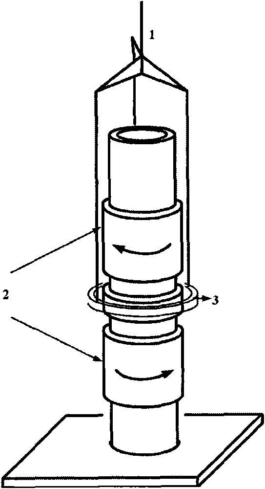
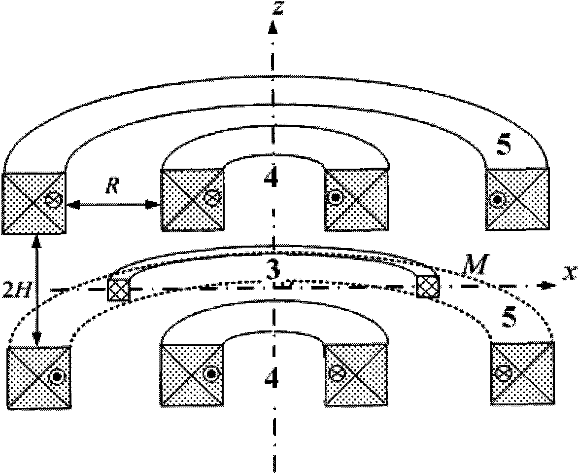
[0063] The mutual induction coil system includes two parts, the movable coil and the fixed excitation coil group, see the attached figure 2 . The movable coil is an ordinary axisymmetric multi-layer thick-walled coil, which is hung on the arm of the precision balance through the suspension system. The key design consideration is the fixed excitation coil set. This is a set of fixed axisymmetric coaxial thick-walled coils that provide a uniform radial magnetic field, so that the movable coil in the radial magnetic field can receive the Lorentz force in the vertical direction after the current is applied.

[0064] F = I 1 I 2 ∂ M ∂ z - - - ( 3 )

[0065] The difficulty in the design of the coil system is to ensure that the radial magnetic fie...


PUM

PropertyMeasurementUnit
The inside diameter ofaaaaaaaaaa
Outer diameteraaaaaaaaaa
The inside diameter ofaaaaaaaaaa

Abstract

The invention relates to a novel mutual inductor system and method for realizing highly uniform mutual inductance quantity vertical gradient in an annular region of a mutual inductor. The novel mutual inductor system is different from the traditional mutual inductor system, and the parameters of the coil and the relative positions of a primary winding and a secondary winding of the mutual inductor are reasonably configured. When the space R between an internal excitation coil and an external excitation coil and the distance H between the excitation coils and a suspension coil meet the equation R2=4 / 3H2 and the turns ratio of the internal excitation coil to the external excitation coil to the suspension coil meets 10000:2700:430, a toroidal magnetic field uniform region with 2 cm axial length can be produced near the symmetrical plane of a Joule balance magnetic field, and the mutual induction parameters of the coil system in the uniform region have four-order uniformity.

Description

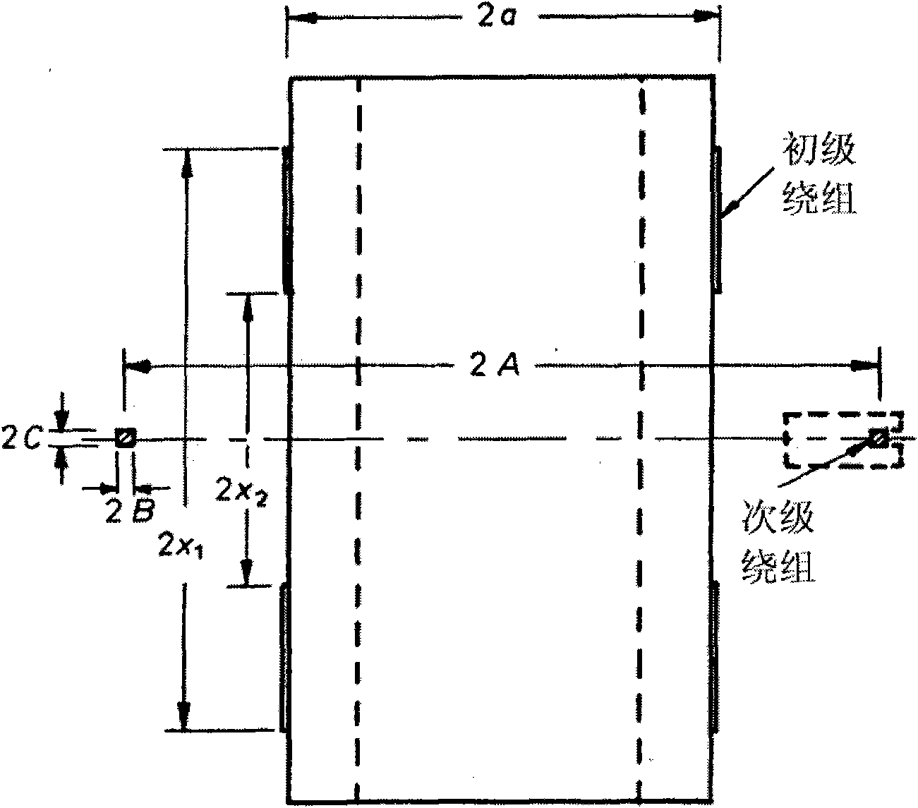
Technical field: [0001] The invention belongs to the field of precision measurement and measurement, and in particular relates to a new method for establishing the mutual inductance coefficient between precision measurement coils. Background technique: [0002] The mutual inductance structure parameter M between coils is determined by the geometric shape, size, number of turns of the mutual inductance coil, the relative position between the coils, whether to fill the magnetic medium, and the nature of the magnetic medium, and has nothing to do with the current in the coil. The main reason why the mutual inductance M is difficult to measure accurately is that the mutual inductance coil itself is an interference signal receiver. When measuring, in order to improve the measurement signal, it is necessary to increase the number of coil turns to increase the mutual inductance coefficient, which also means that the ability to receive interference signals is enhanced. This is also...

Claims


Application Information

Patent Timeline
IPC IPC(8): G01R29/20
Inventor 韩冰贺青张钟华李正坤李辰
Owner NAT INST OF METROLOGY CHINA
Learn More