
Time service method and device for distributed data acquisition units for microseismic monitoring technology

A technology of distributed data and data collectors, applied in the direction of seismic signal transmission, etc., can solve the problems of complex equipment structure and long transmission distance.

Inactive Publication Date: 2011-02-02
北京安科兴业科技股份有限公司
View PDF2 Cites 11 Cited by
  • Summary
  • Abstract
  • Description
  • Claims
  • Application Information

AI Technical Summary

Problems solved by technology

[0005] However, this timing method has the following disadvantages. The data collector is installed underground. To grant the standard time signal obtained from the GPS satellite to the data collector, the standard time signal needs to be transmitted multiple times, and the transmission distance is long. The required equipment complex structure

Method used


Image

  • Time service method and device for distributed data acquisition units for microseismic monitoring technology
  • Time service method and device for distributed data acquisition units for microseismic monitoring technology
  • Time service method and device for distributed data acquisition units for microseismic monitoring technology

Examples


Embodiment 1

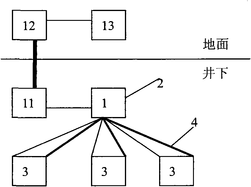
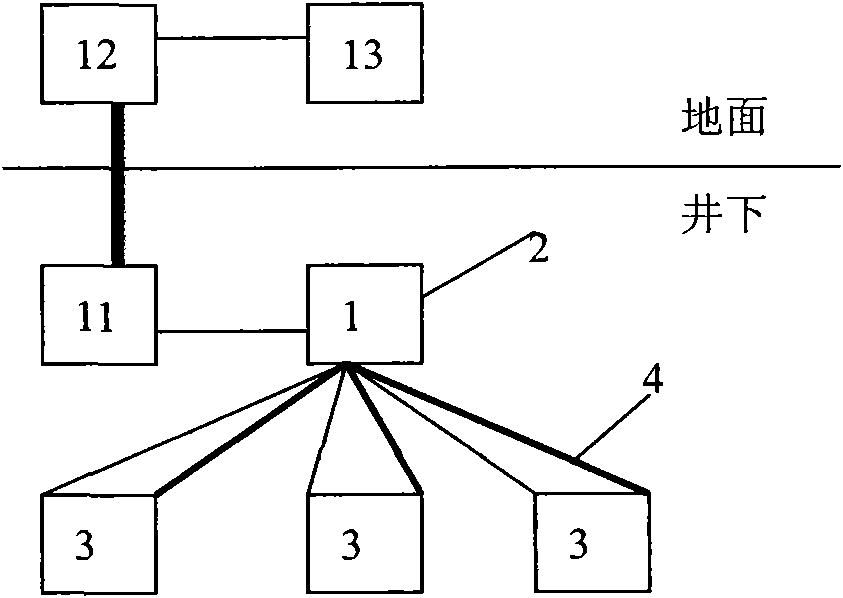
[0016] Such as figure 1 As shown, a timing method for distributed data collectors used in microseismic monitoring technology, an underground monitoring host 1 is installed underground, and a timer 2 is installed in the underground monitoring host, which is connected to the data collector 3 through a signal and synchronization line 4 , to grant time to each data collector, so that each data collector maintains synchronous monitoring.

[0017] The vibration signal collected by the data collector 3 includes information such as the start time of the vibration, the duration of the vibration, and the vibration amplitude. The timer 2 is set to provide time service to each data collector 3, so that the data collection time of the distributed data collectors 3 is kept synchronized, and the sampling frequency of each data collector is also kept consistent.

[0018] The data collected by the data collector 3 is transmitted to the downhole monitoring host 1, and then to the ground data p...

Embodiment 2

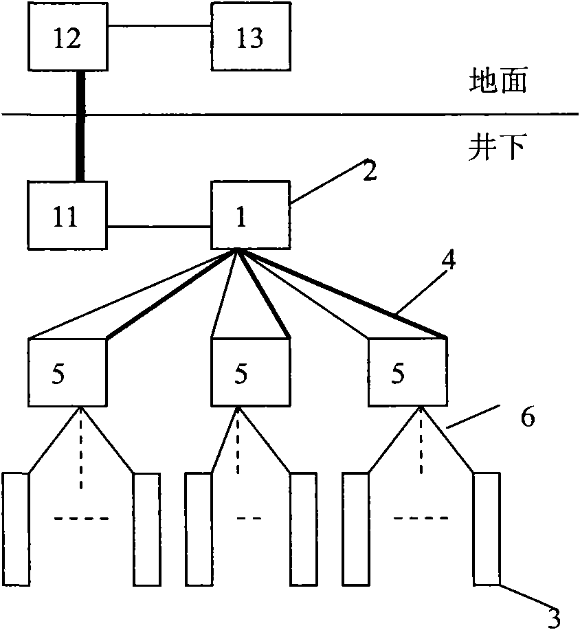
[0021] A timing method for a distributed data collector used in microseismic monitoring technology. An downhole monitoring host 1 is installed underground, and a timer 2 is installed in the downhole monitoring host. The downhole substation 5 is connected to the downhole substation 5 through a signal and synchronization line 4, and the time Granted to each underground substation 5, so that each underground substation 5 maintains synchronous monitoring.

[0022] Each downhole substation 5 connects several data collectors 3 with cables 6 , and since each substation maintains synchronous monitoring in time, the synchronous monitoring of all data collectors 3 is realized.

[0023] The vibration signal collected by the data collector 3 includes information such as the start time of the vibration, the duration of the vibration, and the vibration amplitude. Set the timer 2 to the underground substation 5, and the time and sampling frequency of the data collector 3 are consistent with ...


PUM


Abstract

The invention relates to a time service method and a time service device for distributed data acquisition units for microseismic monitoring technology. An underground monitoring host is arranged underground; a time server is arranged in the underground monitoring host, is connected with the data acquisition units through signals and sync cords and provides time service for each data acquisition unit to make the data acquisition units synchronously perform monitoring; meanwhile, the time server also makes the data acquisition units have the same sampling frequency. The time server also can provide time service for underground substations connected with the plurality of data acquisition units, so that all data acquisition units also can perform monitoring synchronously. The time service method is simple, overcomes the defect that the GPS time service system is complicated and difficult to operate, is flexible and effective to use, and has high practical value and wide application prospect.

Description

technical field [0001] The invention relates to a timing method and device for a distributed data collector used in microseismic monitoring technology, in particular to a device and method for implementing distributed monitoring of measuring points in microseismic monitoring technology to realize synchronous monitoring of each measuring point. Background technique [0002] Microseismic technology is a research hotspot at home and abroad this year. It is used for vibration monitoring of coal mines, mainly including SOS, ARAMIS in Poland, ESG in Canada, SUMIT in Germany, ISS in South Africa, Beijing Xinlin Mine Seismic System, CSIRO in Australia, etc. The products and technologies of the unit mainly include distributed and centralized in terms of measuring point layout. [0003] The distributed layout of the measuring points is to set up the downhole monitoring host in the underground, and the host is connected to each measuring point, and each measuring point is equipped with...

Claims


Application Information

Patent Timeline
IPC IPC(8): G01V1/22
Inventor 姜福兴
Owner 北京安科兴业科技股份有限公司
Learn More