
Three-directional composite self-lubricating sliding bearing for main shaft of wind turbine set

A technology for wind turbines and sliding bearings, applied in sliding contact bearings, shafts and bearings, bearing components, etc., can solve the problems of increased frictional resistance, low bearing reliability, fatigue crushing and crushing, etc., and achieves extended service life and simple structure. The effect of compactness and improved stress state

Active Publication Date: 2011-02-02
DALIAN SANHUAN COMPOSITE MATERIAL TECH DEV +1
View PDF9 Cites 4 Cited by
  • Summary
  • Abstract
  • Description
  • Claims
  • Application Information

AI Technical Summary

Problems solved by technology

[0003] 1. When the cylindrical rolling body is in circular motion, the rolling body is not a pure rolling motion due to the difference in linear velocity at both ends, resulting in stagnation, jamming and slippage between friction pairs; because the rolling body, inner and outer rings are rigid , cannot correct the eccentric load condition caused by the tilting of the main shaft, so that the cylindrical rolling element works under the eccentric load condition; both phenomena increase the friction resistance and accelerate the wear of the rolling element and the channel, and the bearing service life is short
[0004] 2. Because the rolling bearing does not have good anti-seismic performance, it is easy to generate vibration under the action of wind and bear a large impact load, and because the actual load of the rolling bearing is point contact or line contact, the rolling body is under a large impact load It is prone to fatigue crushing and crushing, and the reliability of the bearing is low;
[0005] 3. When the wind turbine is started, stopped or operated at low speed, and the frictional working surface cannot effectively establish a dynamic pressure lubricating oil film and is in boundary lubrication or even dry friction, adhesive wear will occur between the friction pairs, and the bearings will be easily damaged;
[0006] 4. Complex structure, large volume and weight, troublesome installation and high cost

Method used


Image

  • Three-directional composite self-lubricating sliding bearing for main shaft of wind turbine set
  • Three-directional composite self-lubricating sliding bearing for main shaft of wind turbine set
  • Three-directional composite self-lubricating sliding bearing for main shaft of wind turbine set

Examples


Embodiment 1

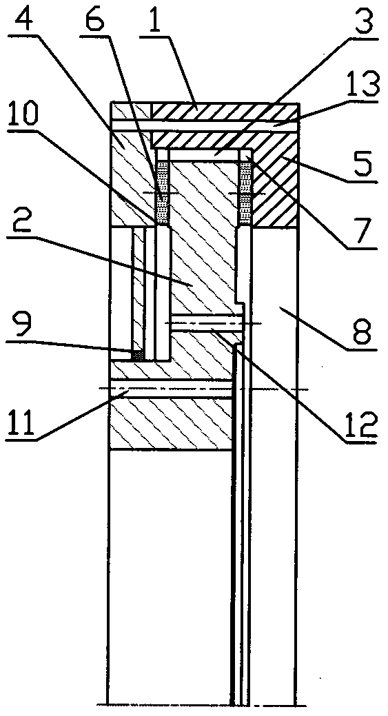
[0022] Such as figure 1 Shown: Same as the prior art, there is an outer ring 1 of a fixed part and an inner ring 2 of a rotating part, and there are a plurality of radial tiles 3 evenly distributed on the circumference between the outer ring 1 and the inner ring 2, and the radial tiles 3 are fixed On the inner surface of the outer ring 1, the inner ring 2 is provided with a connection hole 11 connected to the hub and a connection hole 12 connected to the gearbox in the wind turbine. The difference from the prior art is that the outer ring 1 is axially The left side is connected with the inward left thrust ring 4, and the inward right thrust ring 5 is connected with the axial right side of the outer ring 1. The right thrust ring 5 can be integrated with the outer ring 1, and the left thrust ring 4. The outer circumference can be connected with the outer ring 1 through bolt holes 13, etc., and seals or sealants are arranged at the joint. The inner hole of the left thrust ring 4 ...

Embodiment 2

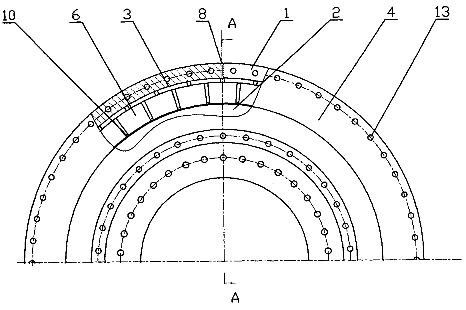
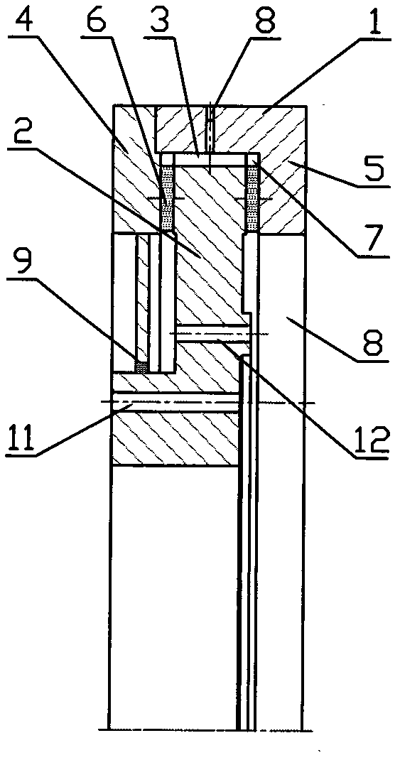
[0025] Such as figure 2 , image 3 As shown, in order to further improve the lubricating effect, on the basis of Embodiment 1, an oil injection hole 8 can be added in the radial direction of the outer ring 1 . During work, the lubricating oil can enter the three pairs of friction pairs through the radial oil hole of the outer ring 1 and the inner hole of the right thrust ring 5 to lubricate.

Embodiment 3

[0027] Such as Figure 4 , Figure 5 Shown: Same as the prior art, there is an outer ring 1 of a fixed part and an inner ring 2 of a rotating part, and there are a plurality of radial tiles 3 evenly distributed on the circumference between the outer ring 1 and the inner ring 2, and the radial tiles 3 can be It is fixed on the inner surface of the outer ring 1, and can also be fixed on the outer surface of the inner ring 2. The inner ring 2 is provided with a connecting hole 11 connected with the hub. The difference from the prior art is that the axis of the outer ring 1 is left There is an inward left thrust ring 4 on the side, and an inward right thrust ring 5 is connected to the axial right side of the outer ring 1. The right thrust ring 5 can be integrated with the outer ring 1, and the left thrust ring 4 The outer circumference can be connected with the outer ring 1 through bolt holes 13, etc., and seals or sealants are arranged at the joints. The inner holes of the left ...


PUM


Abstract

The invention discloses a three-directional composite self-lubricating sliding bearing for a main shaft of a wind turbine set, which has simple structure, convenient installation and disassembly and low cost, can avoid eccentric loading, can bear larger and multi-directional loads, is safe and reliable, has long service life and is provided with an outer ring (1) and an inner ring (2). A plurality of uniformly-distributed radial pads (3) are arranged between the outer ring (1) and the inner ring (2), an inward left thrust ring (4) is connected with the axial left side of the outer ring (1), an inward right thrust ring (5) is connected with the axial right side of the outer ring (1), a plurality of uniformly-distributed axial thrust pads (6) are respectively arranged between the left thrust ring (4) and the inner ring (2) and between the right thrust ring (5) and the inner ring (2), the radial pads (3) and the axial thrust pads (6) are provided with communicated lubricating passages (7), and the lubricating passages (7) are communicated with an oil filling hole (8).

Description

Technical field: [0001] The invention relates to a wind turbine main shaft bearing, in particular to a wind turbine main shaft three-way combination automatic bearing with simple structure, convenient installation and disassembly, low cost, avoiding partial load, and capable of bearing large multi-directional loads, which is safe, reliable and has a long service life. Lubricate plain bearings. Background technique: [0002] The wind turbine is a kind of power generation equipment working at high altitude, and its main shaft bearing is one of the key components of the unit. In addition to bearing the self-weight of the rotating parts such as the hub and the axial positive and negative thrust under the action of wind force, the wind turbine main shaft bearing also bears the overturning moment load formed between the hub and the bearing under the hub's own weight and wind force. Bearings operate under multi-directional stress conditions. The main shaft bearings of existing la...

Claims


Application Information

Patent Timeline
IPC IPC(8): F16C23/04F16C33/74F16C33/10
Inventor 孙承玉于颂东郑东旭刘长波刘彦非
Owner DALIAN SANHUAN COMPOSITE MATERIAL TECH DEV
Learn More