
Sound source localizing method

A sound source localization and sound source technology, which is applied to positioning, direction or offset systems, direction finders using ultrasonic/sonic waves/infrasonic waves, etc., can solve low efficiency, wrong estimation results, and inability to realize three-dimensional sound sources Positioning and other issues, to achieve the effect of simple use and wide application

Inactive Publication Date: 2012-07-11
JIAXING UNIV
View PDF0 Cites 2 Cited by
  • Summary
  • Abstract
  • Description
  • Claims
  • Application Information

AI Technical Summary

Problems solved by technology

[0029] 2. It can only be performed in the time-frequency domain, so the use is limited and not flexible enough
Moreover, when the short-time Fourier transform (STFT) is performed on the time-domain signal, the error of the transformation may directly lead to wrong estimation results;
[0030] 3. When using phase angle analysis to estimate the direction of arrival, when the arcsine term is greater than 1, the estimation result is a complex number and the estimation fails. At this time, another set of frequency response functions needs to be artificially selected for estimation, so the efficiency of the method is compared low and unstable;
[0031] 4. Since the signal receiving array is a one-dimensional linear array, it can only estimate the DOA of the sound source in one direction and cannot realize the three-dimensional positioning of the sound source
[0032] It can be seen that the existing sound source localization methods cannot effectively realize the three-dimensional spatial localization of multiple aliasing sound sources, and there are problems such as inflexible use of localization methods, unstable estimation results, low precision, and insufficient practicability.

Method used


Image

  • Sound source localizing method
  • Sound source localizing method
  • Sound source localizing method

Examples


specific Embodiment

[0070] A specific embodiment of the present invention, a sound source localization method, the specific steps are as follows:

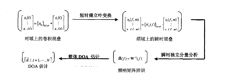
[0071] 1) Considering different application backgrounds, the transient aliasing model and the convolutional aliasing model of the sound source signal are established. The actual application situation is considered in the modeling, that is, the external noise component is included;

[0072] When a narrowband signal s(t) with a bandwidth of W enters a receiving array from the far field, the array has M receiving array elements and each array element is arranged at equal intervals. When a signal arrives at another array element from one array element, it will experience a time delay τ, which depends on the signal's direction of arrival (DOA) angle θ and the array element spacing Δ (wavelength unit). If τ is much smaller than the reciprocal of W (ie Wτ□1), the phase shift between two adjacent array elements At this time, the M-dimensional array observat...


PUM


Abstract

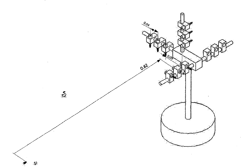
The invention relates to a sound source localizing method. The method comprises the following steps of: establishing an aliasing model of sound source signals; collecting a mixed acoustic signal of a sound source to be tested in the three directions of X, Y and Z by adopting a three-dimensional acoustic measurement array; acquiring a clean observation signal through denoising treatment; estimating a separating matrix of the tested sound source and acquiring a frequency response matrix; once acquiring the accurate estimation of the wave arrival directions of all the sound source signals by adopting a whole wave arrival direction estimation strategy based on peak detection; calculating space angles by utilizing relative space geometric knowledge; and finally, realizing the space localization of the sound source signals. The invention overcomes the defect that a traditional sound source localizing method can not realize the three-dimensional space localization of a plurality of aliasing sound sources and has the problems of inflexible use, unstable estimation result, lower accuracy, poor practicability, and the like.

Description

technical field [0001] The invention relates to a sound source localization method, in particular to a mechanical sound source signal localization method, in particular to a three-dimensional sound source localization method based on wavelet packet decomposition and denoising and independent component analysis. Background technique [0002] Direction of Arrival (DOA) estimation is a main research content of array signal processing. DOA estimation is to determine the orientation of the signal and measure the direction of the signal from the received data. Regardless of whether the signal is a useful signal or an interference signal, it appears as a peak in the DOA estimation pattern, but this peak is not the actual array output power. In acoustic research and application, array signal processing technology has been widely used, especially in sound source localization. [0003] The array processing of acoustic signals first needs to obtain multi-channel acoustic signals with...

Claims


Application Information

Patent Timeline
Patent Type & Authority Patents(China)
IPC IPC(8): G01S5/18G01S3/802
Inventor 焦卫东
Owner JIAXING UNIV
Learn More