Coherent phase detecting method based on Mach-Zehnder interferometer
A fiber optic interferometer and fiber optic interference technology, which is applied in the field of optical quantity detection, can solve the problems that the phase modulation quantity is not easy to realize, and achieve the effects of low cost, simple operation and good precision
Inactive Publication Date: 2011-01-26
JILIN UNIV
View PDF0 Cites 12 Cited by
- Summary
- Abstract
- Description
- Claims
- Application Information
AI Technical Summary
Problems solved by technology
Precise amount of phase modulation is not easy to achieve due to the nonlinear nature of piezoelectric crystals (PZT)
Method used
View moreImage
Smart ImageViewing Examples


Examples
Embodiment 1
Embodiment 2
Embodiment 3
Login to View More PUM
 Abstract
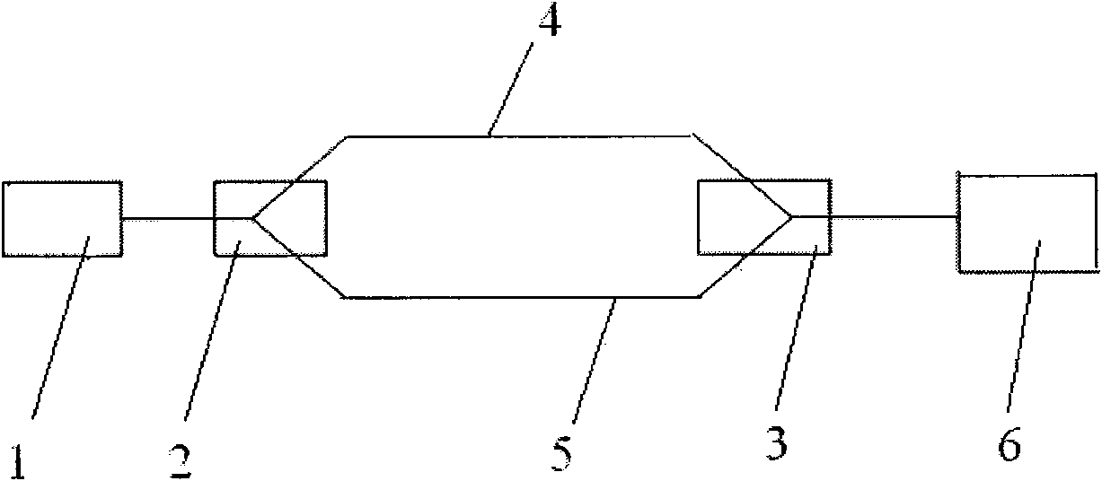
The invention discloses a coherent phase detecting method based on a Mach-Zehnder interferometer, belonging to the technical field of optical quantity detection. Lasers emitted by a laser source (1) are divided into two paths through a first optical fiber coupler (2) and then are respectively transmitted by a first optical fiber interference arm (4) and a second optical fiber interference arm (5); the first optical fiber interference arm (4) and the second optical fiber interference arm (5) are putted into the same constant-temperature control system; two paths of lasers are combined into one path in a primary phase difference detection process, and the photocurrent intensity Io of the combined laser is detected by using a photoelectric diode detector; the intensities I1, I2 of photocurrents output from the two optical fiber interference arms are respectively detected; and the primary phase difference of the two optical fiber interference arms is calculated by using a formula. The invention has the advantages of simple operation and low cost because of no use of a phase shifter of a piezoelectric crystal and the like; a computer is not used to assist calculation, and the measurement precision is superior to 0.04 and better precision can be obtained under larger laser drive current.
Description
technical field The invention belongs to the technical field of optical quantity detection, in particular to a fine detection method for the initial phase difference of coherent light. Background technique The earliest uses of Mach-Zehnder interferometers were in sensors. It has two interference arms, one is called the reference arm, and the other is called the detection arm, and the detection arm is used to put it into the environment to be measured. Due to the influence of the environment to be measured, after the light transmitted in the detection arm obtains a new phase difference relative to the light in the reference arm, the movement of the interference fringe can be observed on the output detector. Measure changes in physical quantities in the environment. Using this principle, small changes in temperature, current, voltage, pressure, magnetic field, etc. can be measured. Another important application of Mach-Zehnder interferometer is in optical communication. Th...
Claims
Login to View More Application Information
Patent Timeline
 IPC IPC(8): G01J9/02
Inventor 吴戈田小建高博汝玉星单江东
Owner JILIN UNIV
Features
- R&D
- Intellectual Property
- Life Sciences
- Materials
- Tech Scout
- Unparalleled Data Quality
- Higher Quality Content
- 60% Fewer Hallucinations
Learn More Browse by: Latest US Patents, China's latest patents, Technical Efficacy Thesaurus, Application Domain, Technology Topic, Popular Technical Reports.
© 2025 PatSnap. All rights reserved.Legal|Privacy policy|Modern Slavery Act Transparency Statement|Sitemap|About US| Contact US: help@patsnap.com