
Annular thin-wall article clamping device and using method thereof

A technology of clamping device and thin-walled parts, which is applied in the direction of positioning device, clamping, tool holder accessories, etc., can solve the problems that affect the production efficiency of enterprises, spend a lot of time on alignment, and affect the positioning accuracy of workpieces, so as to ensure accurate Sexuality, time-saving, and productivity-enhancing effects

Active Publication Date: 2011-01-26
DONGFANG TURBINE CO LTD
View PDF7 Cites 110 Cited by
  • Summary
  • Abstract
  • Description
  • Claims
  • Application Information

AI Technical Summary

Problems solved by technology

However, regardless of the mold clamping method or the traditional several clamping methods, they can only achieve one-time clamping and can only realize the processing of the wall surface on one side (inside or outside) of the workpiece, and the processing of the wall surface on the other side of the workpiece. have to be re-clamped, which will take a lot of time and affect the production efficiency of the enterprise
What's more, because of the re-clamping of several traditional clamping methods, it takes a lot of time to find the alignment and positioning accuracy of the workpiece. Even so, the positioning accuracy of the workpiece after re-clamping will be directly affected

Method used


Image

  • Annular thin-wall article clamping device and using method thereof
  • Annular thin-wall article clamping device and using method thereof
  • Annular thin-wall article clamping device and using method thereof

Examples


Embodiment Construction

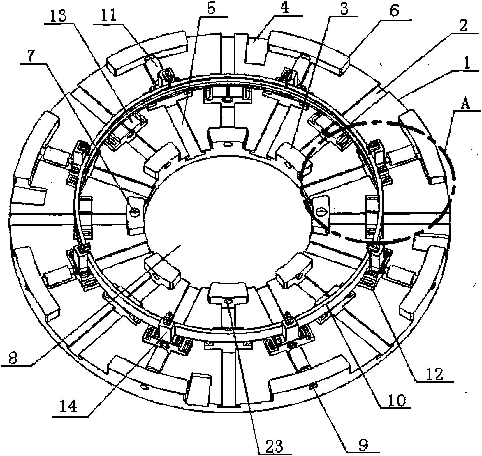
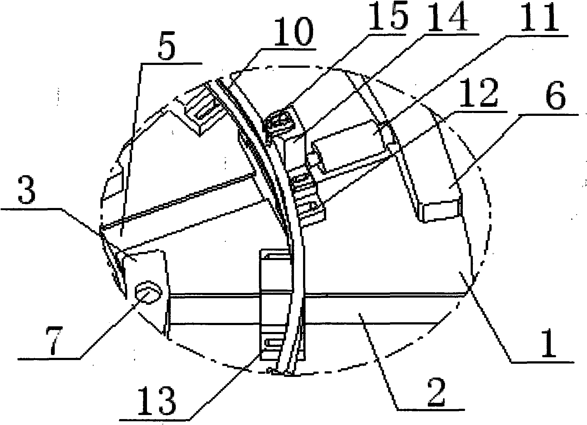
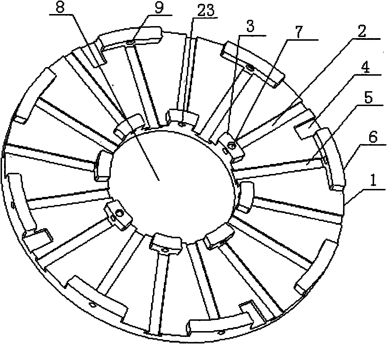
[0049] see Figure 1 to Figure 4 , the present invention includes an annular chassis 1, the diameter of the chassis 1 is at least 2800mm, such as 3600mm, 4200mm, 5500mm or 62000mm, etc., and the inner circle 8 of the chassis 1 has a maximum diameter of 1000mm, such as 900mm, 750mm, 600mm or 500mm, etc. . Its clamping coverage is large, and it can be suitable for clamping workpieces of various sizes and specifications. Four pressing grooves 4 are arranged on the outer circumference of the chassis 1 .

[0050] A radial adjustment mechanism for positioning the workpiece 10 is provided on the annular chassis 1. The radial adjustment mechanism is composed of a push rod and a slider. The radial adjustment mechanism is divided into two groups: the inner radial adjustment mechanism and the outer radial adjustment mechanism, namely the inner radial adjustment mechanism The slider 13 and the ejector rod form an inner radial adjustment mechanism, and the outer slider 12 and the ejector...


PUM

PropertyMeasurementUnit
diameteraaaaaaaaaa
diameteraaaaaaaaaa

Abstract

The invention provides an annular thin-wall article clamping device and a using method of the device. The clamping device comprises an annular chassis; the chassis is provided with a radial regulation mechanism of a locating workpiece; the radial regulation mechanism is divided into an inner radial regulation mechanism and an outer radial mechanism; two radial regulation mechanisms position workpiece respectively from the inner side or the outer side of the workpiece; the chassis is respectively provided with track-directed sliding grooves for the two radial adjustment mechanisms; the inner end of the sliding groove of the inner radial regulation mechanism is provided with a stopping block; the outer end of the sliding groove of the outer radial regulation mechanism is provided with the stopping block; the sliding grooves of the two groups of radial regulation mechanisms are disposed at intervals; one of the two groups of radial regulation mechanisms is provided with an axial compacting mechanism for fixing the workpiece; and the axial compacting mechanism is displaced alternatively between the two groups of radial regulation mechanisms when turning the workpiece. The clamping device can realize the processing of two side walls of the workpiece by clamping the workpiece once, and is fit for the clamping of the workpieces with different specifications. The device has the characteristics of high use rate, strong practical applicability, good generality, time saving and labor saving, light labor intensity, high production efficiency and the like.

Description

Technical field: [0001] The invention relates to a clamping device for ring-shaped thin-walled parts, in particular to a clamping device for ring-shaped thin-walled parts and a method for using the device. It is especially suitable for turning and clamping of large annular thin-walled parts such as gas turbine shrouds, and can also be used for turning and clamping of other annular thin-walled parts. Background technique: [0002] Thin-walled parts have the characteristics of light weight, material saving, and compact structure, and have been widely used in industrial production. However, for a long time, thin-walled parts have been difficult to process in machining because of their poor rigidity and weak strength, they are easily deformed during processing, the processing quality is not easy to guarantee, and the product qualification rate is low. It is an annular thin-walled part. [0003] Annular thin-walled parts are usually processed by CNC turning, because of the diff...

Claims


Application Information

Patent Timeline
Patent Type & Authority Applications(China)
IPC IPC(8): B23Q3/06B23B5/00B23B13/00B23B15/00
Inventor 巩丽陈仲明唐仕东胡丽萍胡建军彭刚隆希斌刘祥李旭王梦雄
Owner DONGFANG TURBINE CO LTD
Learn More