


Quick Research
Generate reliable direction feasibility study reports for your R&D in just a few steps.

Technical Q&A
Discover and master advanced knowledge NOW. Basics, ideas, possibilities, all at once.

Find Solutions
As an expert in R&D theories, this can generate solutions to your technical problems instantly.

Evaluate Feasibility
Analyze your overall solution with one click, know your potential R&D risks in advance.

Monitor Landscape
Get weekly tech updates, stay abreast of the latest tech innovations and key insights.
Display device
A display device and display panel technology, which is applied to identification devices, optics, instruments, etc., can solve the problems of phosphor scattering, large reflection, and display quality degradation, and achieve excellent tolerance, increase display brightness, and suppress display quality degradation Effect
- Summary
- Abstract
- Description
- Claims
- Application Information
AI Technical Summary
Problems solved by technology
Method used
Image


Examples
Embodiment 1、 comparative example 1、2、3、4
[0066] Trial production has and figure 1 The liquid crystal display device 100A shown is a liquid crystal display device of the same structure. As the plastic layer 12, a sheet with a thickness of 0.5 mm of COP (cycloolefin polymer) produced by injection molding was used. The COP sheet has a slow axis in the resin flow direction and a retardation of 28 nm. Here, the COP sheet is used as the protective layer.
[0067] A stretched film of COP is used as the quarter-wavelength layer. The retardation of this COP stretched film at a wavelength of 550 nm was 138 nm.
[0068] The slow axis (or advance axis) of the plastic layer 12 is arranged parallel to the transmission axis of the polarizing layer 16, and the slow axis of the quarter-wave layer 14 is arranged at an angle of 45° to the transmission axis of the polarizing layer 16.
[0069] In addition, on the surface of the polarizing layer 16, the antireflection layer 18 having a structure (moth-eye structure) in which the refractive ...
Embodiment 2
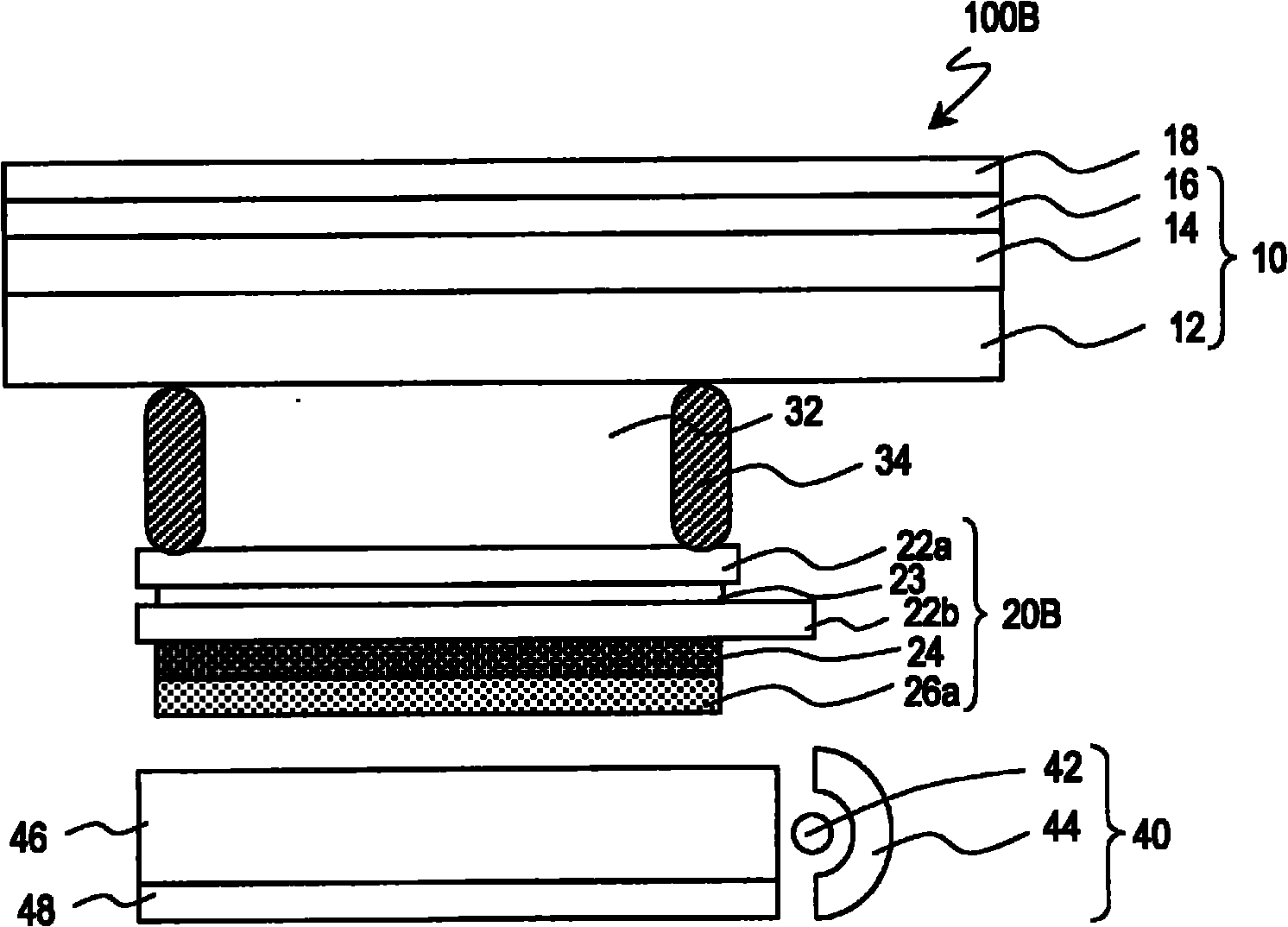
[0086] Trial production has and image 3 The liquid crystal display device 100B shown is a liquid crystal display device of the same structure. As in Example 1, a vertical alignment type liquid crystal display panel was used, and the transmission axis of the polarizing layer 26a of the liquid crystal display panel 20B and the transmission axis of the polarizing layer 16 of the optical plate 10 were arranged orthogonally.
[0087] As shown in Table 2, it can be seen that the reflectance and the results of visual evaluation are as good as the liquid crystal display device of Example 1, and the transmittance is improved compared to the liquid crystal display device of Example 1. In addition, the transmittance is a relative value obtained by setting the transmittance (brightness) of the liquid crystal display device of Example 1 to 1. Among the components common to the liquid crystal display device of Example 1, the same or the same batch of materials was used, unnecessary components...
Embodiment 3
[0091] Trial production has and Figure 4 The liquid crystal display device 200 shown is a liquid crystal display device of the same structure. As the liquid crystal cell 54, a parallel alignment type liquid crystal cell using a nematic liquid crystal material with positive dielectric anisotropy was used. The parallel alignment type liquid crystal cell is produced by rubbing the alignment film in anti-parallel. The retardation of the liquid crystal cell 54 when no voltage is applied is 137 nm, and the retardation can be reduced to 10 nm by applying a sufficient voltage.
[0092] The evaluation results of the liquid crystal cell 54 when a voltage is applied to the liquid crystal layer 53 and when no voltage is applied are shown in Table 3. The evaluation of the visibility was performed in addition to the evaluation at 40,000 lux (bright environment), and also under the virtual dark condition of 100 lux (dark environment).
[0093] [table 3]
[0094]
[0095] From the results of Tab...
PUM
| Property | Measurement | Unit |
|---|---|---|
| refractive index | aaaaa | aaaaa |
| reflectance | aaaaa | aaaaa |
| refractive index | aaaaa | aaaaa |
Abstract
Description
Claims
Application Information
 - R&D Engineer
- R&D Manager
- IP Professional
- Industry Leading Data Capabilities
- Powerful AI technology
- Patent DNA Extraction
Browse by: Latest US Patents, China's latest patents, Technical Efficacy Thesaurus, Application Domain, Technology Topic, Popular Technical Reports.
© 2024 PatSnap. All rights reserved.Legal|Privacy policy|Modern Slavery Act Transparency Statement|Sitemap|About US| Contact US: help@patsnap.com