
Protection device of suction type optical disk drive

A technology for protection devices and optical disc drives, which is applied in the direction of recording carrier guidance, instruments, and recording information storage, and can solve the problems of increasing the force of the chute 3, troubles in adjusting the driving force, and consuming manufacturing man-hours, etc.

Inactive Publication Date: 2011-01-12
QUANTA STORAGE INC
View PDF0 Cites 0 Cited by
  • Summary
  • Abstract
  • Description
  • Claims
  • Application Information

AI Technical Summary

Problems solved by technology

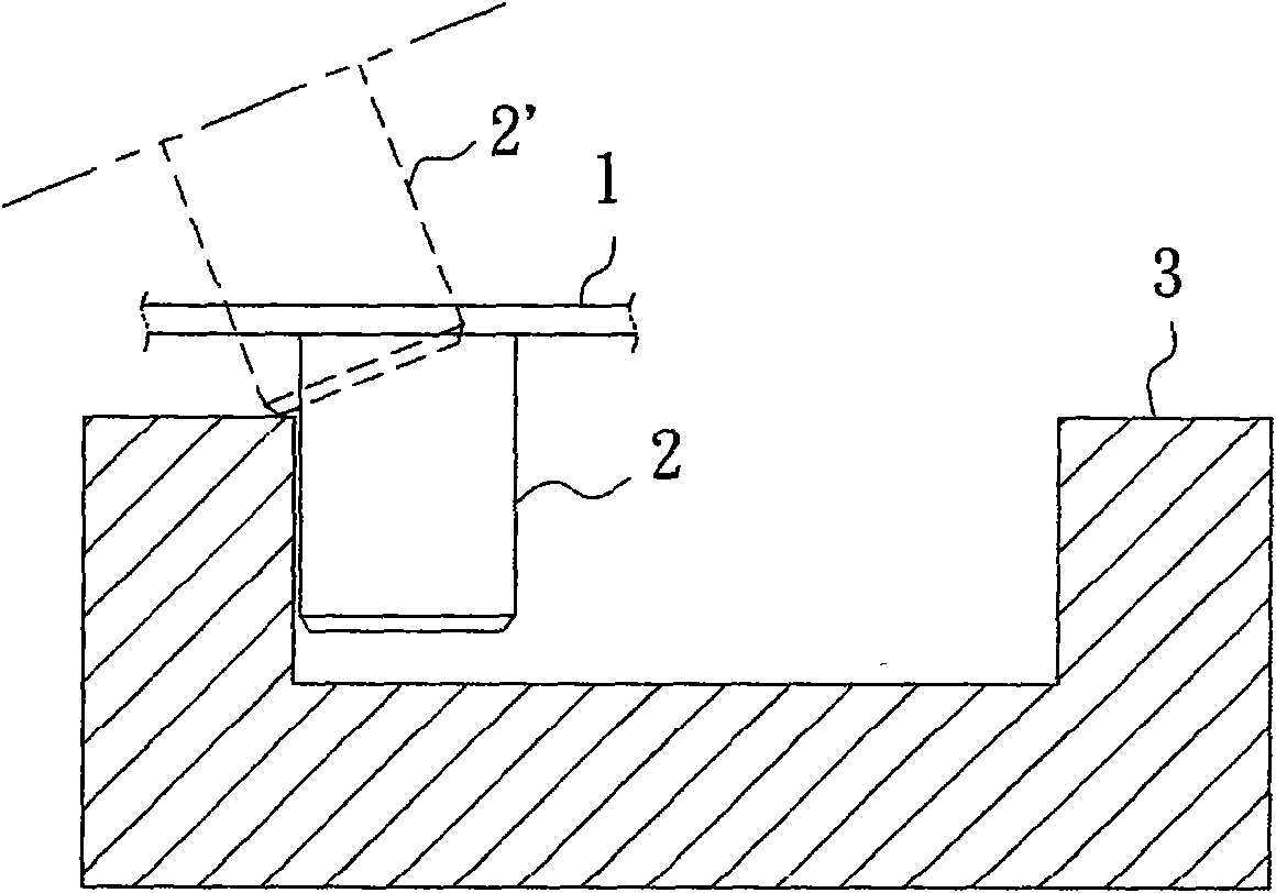
If the driving force of the slot-in optical drive is adjusted too low, although it can reduce the force exerted by the chute 3 on the guide pin 2 and prevent the guide pin 2 from slipping out of the chute 3, the insufficient driving force often cannot advance and retreat the disc smoothly.
Increasing the driving force will easily increase the force exerted by the chute 3 on the guide pin 2, causing the guide pin 2 to slip out of the chute 3, causing troubles in adjusting the driving force and consuming manufacturing man-hours
Furthermore, if the consumer does not use it normally, he releases or pulls the disc slowly, and the smooth guide pin 2 on the side is easy to slip out of the chute 3

Method used


Image

  • Protection device of suction type optical disk drive
  • Protection device of suction type optical disk drive
  • Protection device of suction type optical disk drive

Examples


Embodiment Construction

[0048] In order to achieve the above-mentioned purpose, the technical means adopted and their effects related to the present invention are listed below as preferred embodiments, and are described as follows in conjunction with the accompanying drawings.

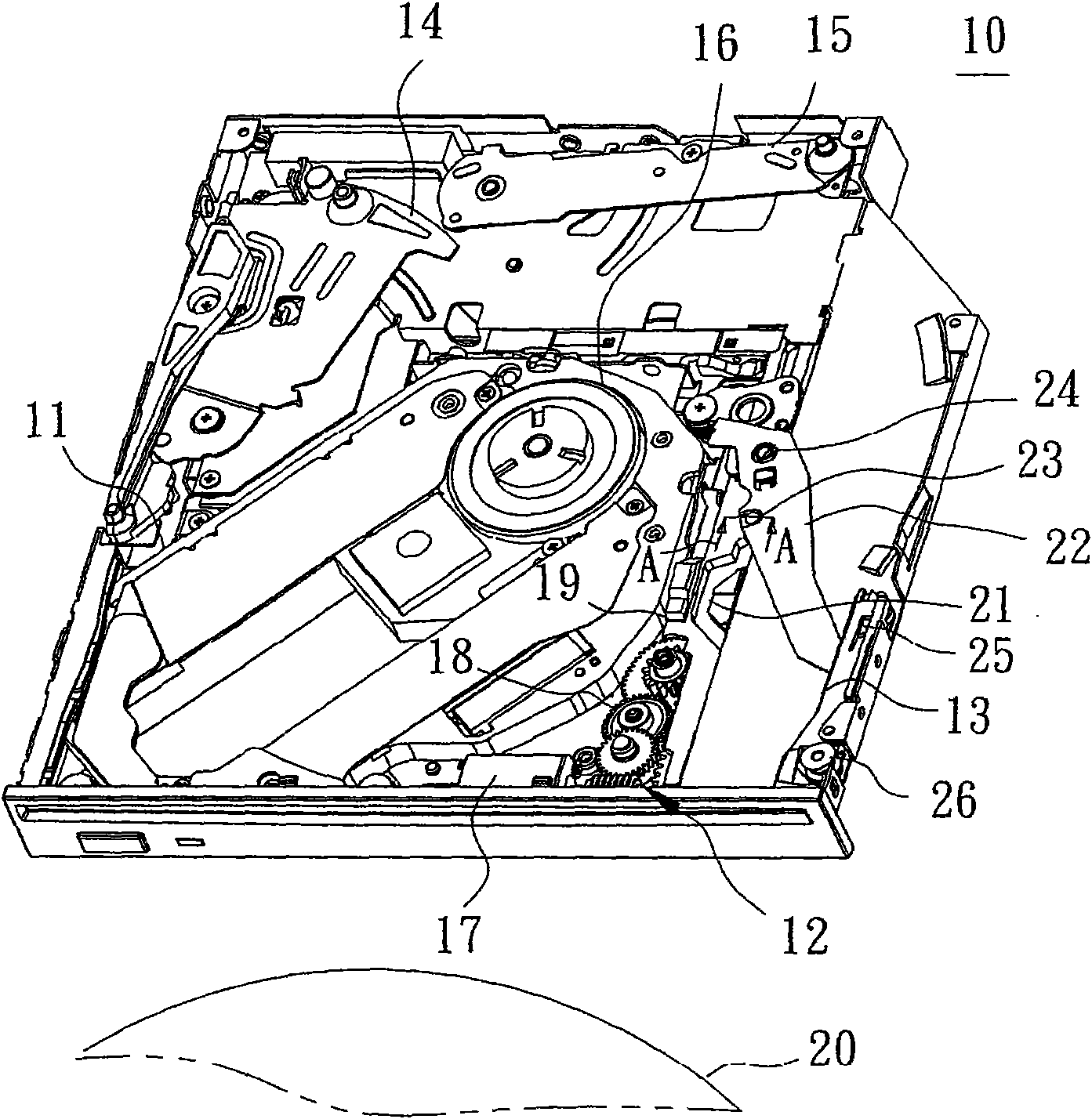
[0049] Please refer to figure 2 , is the slot-in optical disk drive 10 provided with the protection device of the present invention. The slot-in optical disc drive 10 includes a core 11 , a power unit 12 , a film advancing guide rod 13 , a film ejecting guide rod 14 , a positioning guide rod 15 and the like. The core 11 is disposed in the hollow of the slot-in optical disc drive 10 , and one end of the core 11 is provided with a spindle motor 16 and is located in the center of the slot-in optical disc drive 10 . Adjacent to the movement 11, a power unit 12 is arranged, and the power unit 12 utilizes a transmission motor 17 to rotate the gear set 18 to drive the slider 19 to move back and forth along the side of the slot-in ...


PUM


Abstract

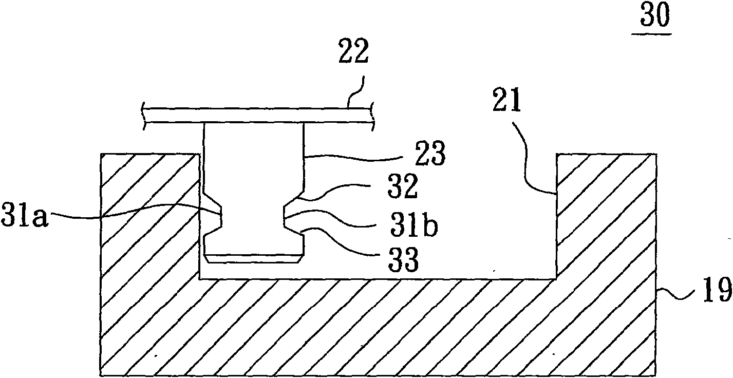
The invention relates to a protection device of a suction type optical disk drive, which is arranged between two linkage members of the suction type optical disk drive. One of the two linkage members is provided with a sliding slot, and the other linkage member is connected at the upper end of a guide pin. The lower end of the guide pin is convexly embedded in the sliding slot, a gap is concavely arranged in the position of the side edge which is opposite to the sliding slot, and the gap is used for clamping the sliding slot, thereby preventing the guide pin from sliding out of the sliding slot. A conductive part which is positioned on a first layer of a circuit board and passes through a second layer of the circuit board is electrically connected with a first microphone.

Description

technical field [0001] The present invention relates to a slot-in optical disc drive, in particular to a protection device for preventing the slipping of the drive member of the retracting film mechanism in the slot-in type optical disc drive. Background technique [0002] The slot-in optical disc drive uses multiple guide rods of the advance and retreat mechanism, and is linked through the drive link to automatically push the disc to the playback position or eject the disc. It is not only simple and convenient to operate, but also easy to thin. It has become the mainstream of current market consumption. . [0003] like figure 1 Shown is the way in which the prior art slot-in optical drive drives the guide rod. Most of the prior art slot-in optical disc drives are equipped with guide pins 2 or chutes 3 on the linked guide rod 1 respectively, and use the chute 3 that swings up and down or left and right to make the guide pin 2 embedded in the chute 3 move smoothly. Sliding...

Claims


Application Information

Patent Timeline
Patent Type & Authority Applications(China)
IPC IPC(8): G11B15/60G11B17/04G11B17/051
Inventor 蔡耀庆吴仁琛
Owner QUANTA STORAGE INC
Learn More