Lens

A technology of lens and light-emitting surface, which is applied in the lens field of light-emitting diode light sources, and can solve the problems that the design of the focusing lens cannot meet the requirements, etc.

Inactive Publication Date: 2011-01-12
NANTONG ZHONGTIE HUAYU ELECTRICS
View PDF1 Cites 6 Cited by
  • Summary
  • Abstract
  • Description
  • Claims
  • Application Information

AI Technical Summary

Problems solved by technology

However, in some occasions, such as flashlights or bicycle lights with LED light sources, it is hoped that the light source can realize the illumination of the distant area and the illumination of the nearby ground area. The above-mentioned focus lens design will not meet the requirements.

Method used


Image

  • Lens
  • Lens
  • Lens

Examples


Embodiment Construction

[0025] The present invention will be described in further detail below in conjunction with the accompanying drawings.

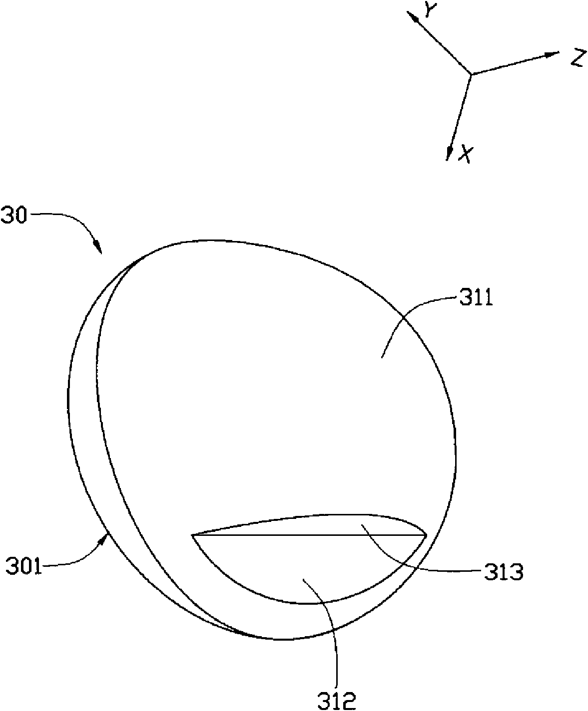
[0026] see image 3 and Figure 4 , the Z-axis is the optical axis OO' direction of the lens 30; the Y-axis is a direction perpendicular to the ground, which is perpendicular to the Z-axis direction; the X-axis is perpendicular to the plane formed by the Y-axis and the Z-axis. The lens 30 provided by the first embodiment of the present invention includes a light incident surface 301 , a first light exit surface 311 , a second light exit surface 312 and a third light exit surface 313 . The light incident surface 301 is perpendicular to the optical axis OO' of the lens 30, the first light exit surface is a convex surface and is arranged on the upper part of the lens 30, that is, the part away from the ground; the second light exit surface 312 is arranged on the lower part of the lens 30, that is, close to the ground part.

[0027] The light-incident surface ...


PUM


Abstract

The invention discloses a lens used for an LED light source, comprising a light incident face and a first light outgoing face, wherein, the light incident face is vertical to a light axis of the lens; the first light outgoing face is a protruding bent face and is relative to the light incident face; the lens also comprises a second light outgoing face which is relative to the light incident face and is adjacently connected with the first light outgoing face; and the thickness close to the part of the light axis of the lens between the second light outgoing face and the light incident face is greater than the thickness far from the part of the light shaft of the lens between the second light outgoing face and the light incident face. Through the design of the lens, lighting regions are formed on a far-field region and a near-field region, thus realizing the function of simultaneously lightening the two regions.

Description

technical field [0001] The invention relates to a lens, in particular to a lens applied to a light emitting diode light source. Background technique [0002] Now, light emitting diodes (Light Emitting Diode, LED) have been widely used in many fields, especially widely used in lighting. Here, a new type of light-emitting diode can be found in the article "Illumination With Solid State Lighting Technology" by Daniel A. Steigerwald et al. in IEEE Journal on Selected Topics in Quantum Electronics, Vol.8, No.2, March / April 2002. [0003] LED is similar to a point light source, and the divergence angle of its light is relatively large. To achieve long-distance lighting, it is generally necessary to install a focusing lens in front of the LED light source to reduce the divergence angle of the LED light so that it is concentrated near the optical axis and emitted. Such as figure 1 As shown, the general convex lens 10 can be used as the focusing lens of the LED light source 11. The...

Claims


Application Information

Patent Timeline
Patent Type & Authority Applications(China)
IPC IPC(8): F21V5/04H01L33/00F21Y101/02
CPCF21V5/04F21V13/04F21V5/00F21V7/0091H01L33/58F21Y2101/02F21Y2115/10
Inventor 陈添宝黄志德
Owner NANTONG ZHONGTIE HUAYU ELECTRICS
Why Eureka
Try Eureka