
Method of taxiing an aircraft

An aircraft and motor technology, applied in aircraft parts, aircraft braking arrangements, wheeled, etc.

Active Publication Date: 2011-01-12
SAFRAN LANDING SYSTEMS
View PDF5 Cites 10 Cited by
  • Summary
  • Abstract
  • Description
  • Claims
  • Application Information

AI Technical Summary

Problems solved by technology

However, the main landing gear wheels are usually fitted with brakes, thus leaving very little room available for a powerful motor

Method used


Image

  • Method of taxiing an aircraft
  • Method of taxiing an aircraft
  • Method of taxiing an aircraft

Examples


Embodiment Construction

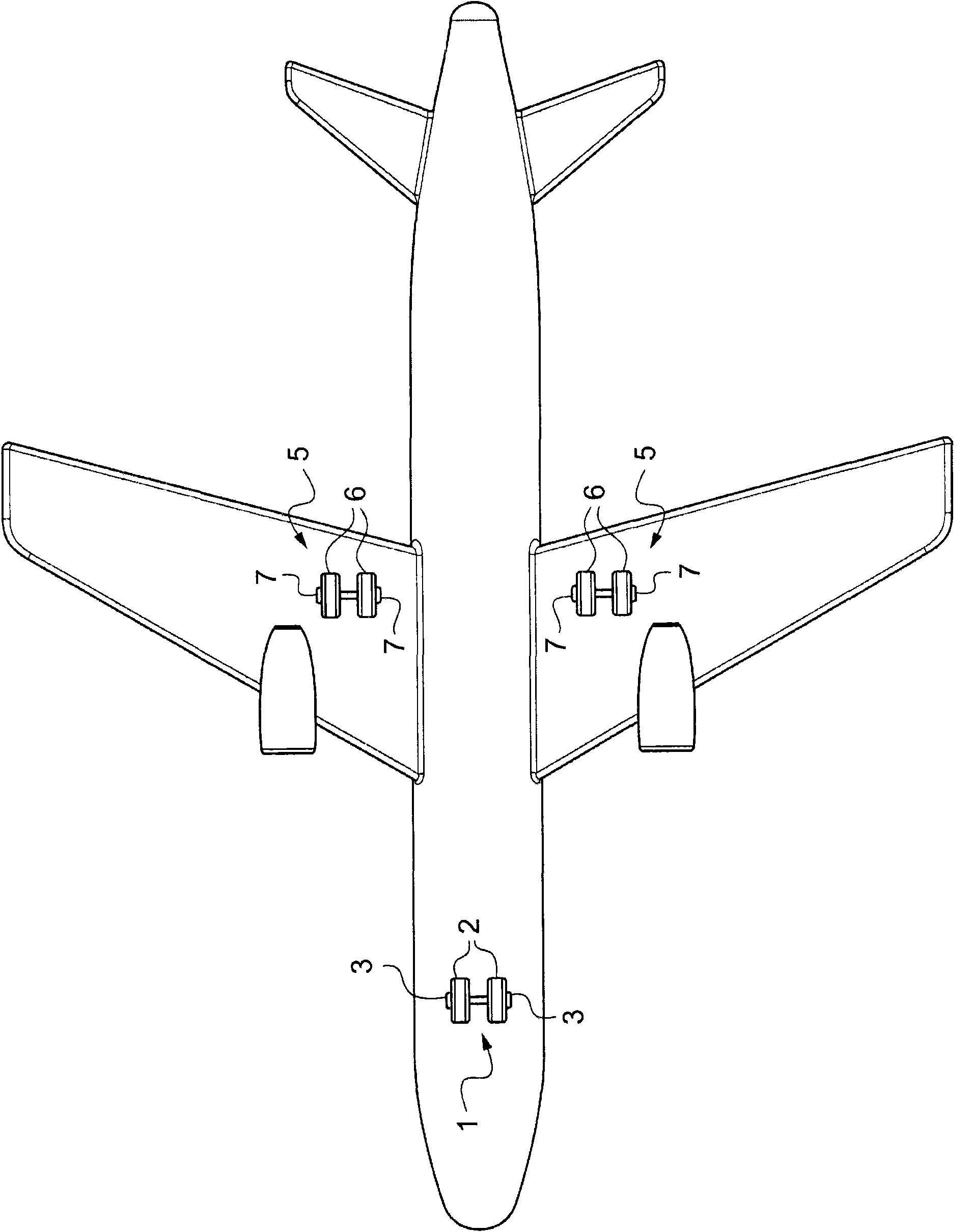
[0023] refer to figure 1 , the aircraft includes a nose landing gear 1 carrying two wheels 2 equipped with corresponding main taxi motors 3 .

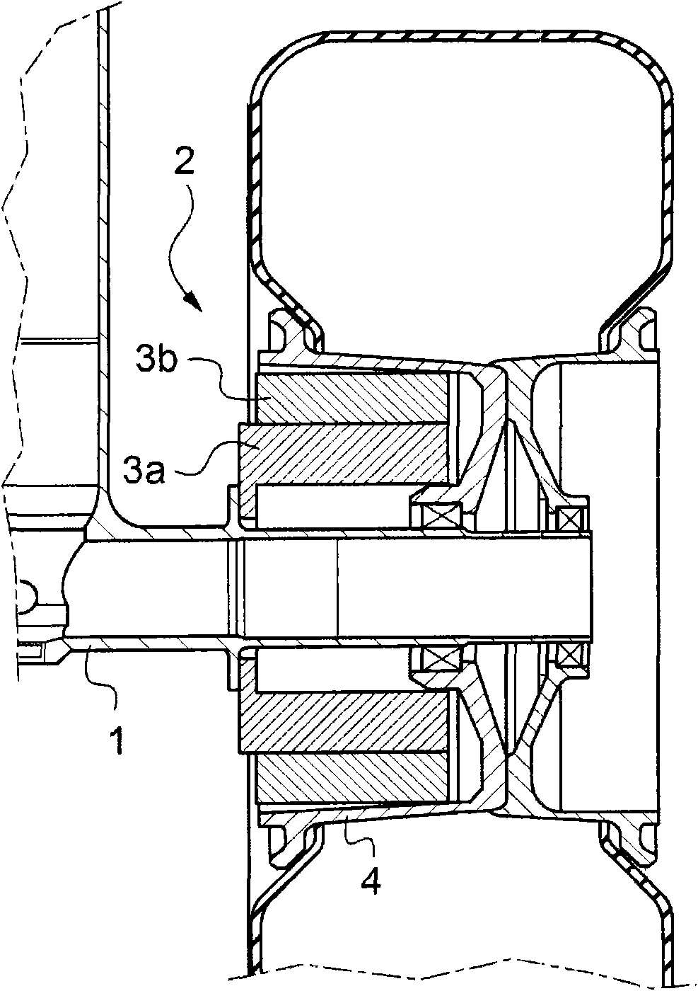
[0024] figure 2 One of the wheels 2 of the nose gear 1 is shown with its hollow rim 4 forming an internal volume adapted to receive a main taxi motor 3 of considerable size. In this example, the main taxi motor comprises a wound stator 3 a fixed to the undercarriage and in electromagnetic relation to a permanent magnet rotor 3 b fixed to the rim of the wheel 2 . In this example, the coast motor comprises a single torque motor type electric motor, preferably without any gears.

[0025] The aircraft also includes two main landing gears 5 each carrying two wheels 6 each equipped with an auxiliary taxi motor 7 .

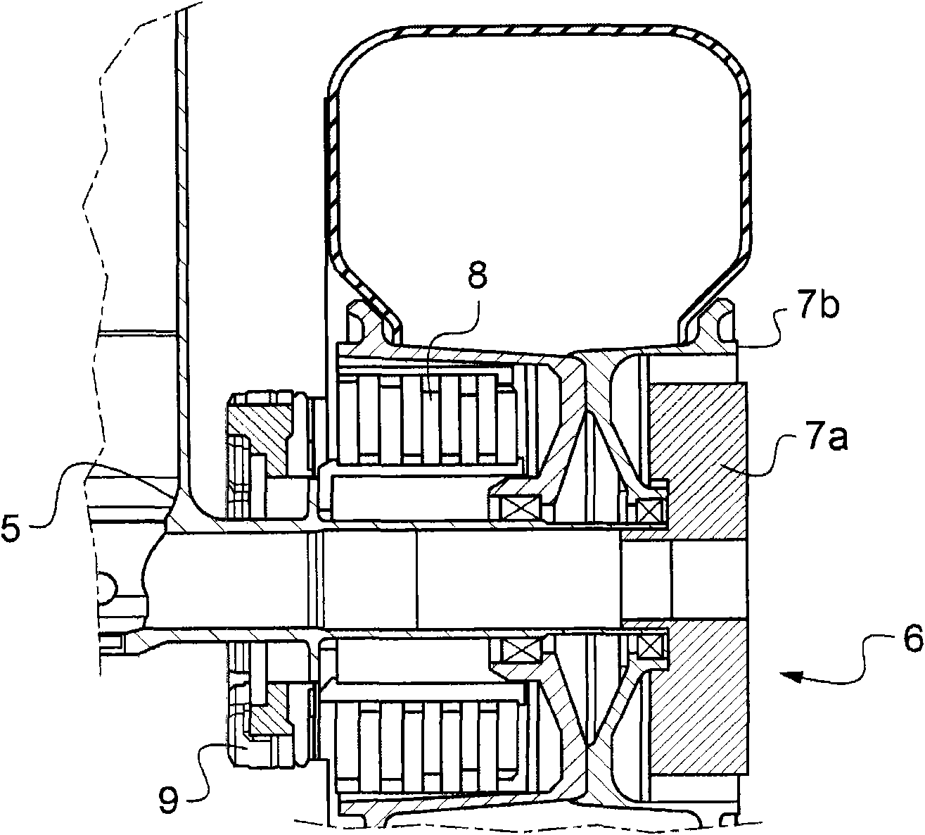
[0026] image 3 One of the two wheels 6 of the main landing gear 5 with a hollow rim is shown. In this example, the internal volume of the rim is mainly occupied by the brake, visible in the figure as a stack of discs 8 and...


PUM


Abstract

The method involves providing one of wheels (2) carried by an auxiliary landing gear (1) of a main displacement motor (3) i.e. torque motor, and providing one of wheels (6) carried by main landing gears (5) of an additional displacement motor (7). The main displacement motor is solicited in response to a displacement order to displace an aircraft in a situation at which driving force of the aircraft developed using the main displacement motor is insufficient to displace the aircraft. The additional displacement motor is solicited in addition to the main displacement motor.

Description

technical field [0001] The invention relates to an aircraft taxiing method. Background technique [0002] In order to allow the aircraft to be steered and taxied on the ground without the thrust of its engines, various proposals have been made to place taxi motors within the wheels of the aircraft's main landing gear. For this purpose, the taxi motor is powered by means of a generator driven by the aircraft's auxiliary power unit. [0003] The main landing gear wheels are usually heavily loaded, so they may need to develop large driving forces. However, the main landing gear wheels are usually fitted with brakes, thus leaving very little room available to receive a powerful motor. To alleviate this lack of space, various structural arrangements have been proposed. [0004] For example, document US 2006 / 065779 proposes to place the taxi motor inside the nose gear wheel which normally does not include brakes. Therefore, a large volume is provided for receiving a large powe...

Claims


Application Information

Patent Timeline
Patent Type & Authority Applications(China)
IPC IPC(8): B64C25/42B64C25/36
CPCB64C25/405Y02T50/823Y02T50/80
Inventor H·查卢尔D·德劳伊
Owner SAFRAN LANDING SYSTEMS
Learn More