Self-adhesion membrane blowing production equipment and production method

A kind of production equipment and technology of self-adhesive film, which is applied in the production equipment and production field of self-adhesive film blowing method, which can solve the problems of self-adhesive film wrinkles, shaking, stickiness, and unwinding smoothly

Active Publication Date: 2011-01-12
GUANGDONG JINMING MACHINERY
View PDF3 Cites 7 Cited by
  • Summary
  • Abstract
  • Description
  • Claims
  • Application Information

AI Technical Summary

Problems solved by technology

[0004] In the self-adhesive film blown film production process of the prior art, when the self-adhesive film bubble is extruded, the adhesive layer is generally located on the outer layer, otherwise, if the adhesive layer is located on the inner layer, the ring-shaped self-adhesive film will be flattened by the splint Finally, the adhesive layers of the annular self-adhesive film will face each other and stick together, so in the subsequent process, it is difficult to rely on the traction force of the take-up mechanism to separate the two adhesive layers, because as we all know, when the take-up mechanism takes up , the surface tension of the coil must be accurately controlled within a certain value range, and the surface tension of the coil in this value range is difficult to separate the two adhesive layers, so it cannot be rolled smoothly
[0005] Based on the above reasons, in the production process of the self-adhesive film blown film method in the prior art, the adhesive layer is generally arranged on the outer layer of the annular bubble, but this will cause the following problems: when the self-adhesive film is advancing, the adhesive layer must pass through And come into contact with the surface of many parts such as foam stabilizer, herringbone splint, film tube traction nip roller, etc., so that the adhesive layer will stick to the surface of many of the above parts, which will not only easily cause wrinkles and shakes of the self-adhesive film, but also affect the self-adhesive film. Viscosity (cohesive force) of the finished mucosa

Method used


Image

  • Self-adhesion membrane blowing production equipment and production method
  • Self-adhesion membrane blowing production equipment and production method
  • Self-adhesion membrane blowing production equipment and production method

Examples


Embodiment 1

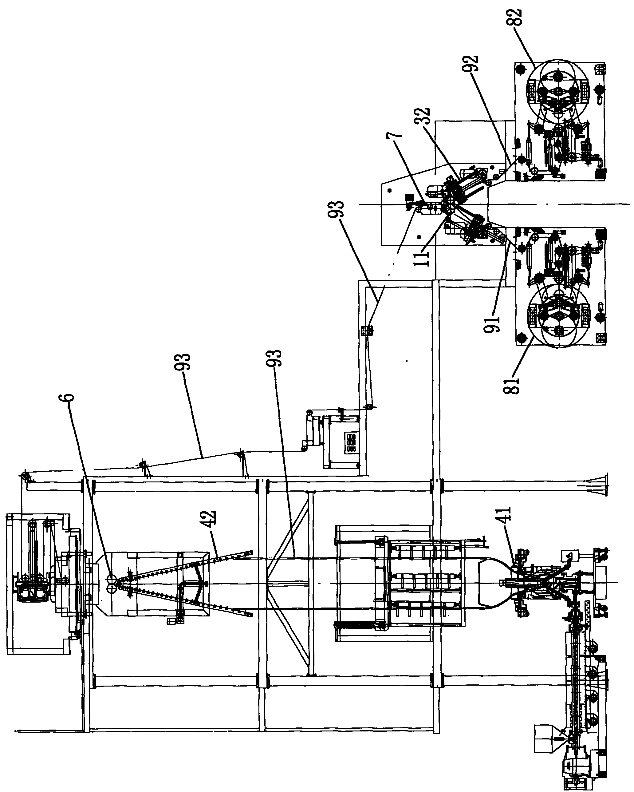
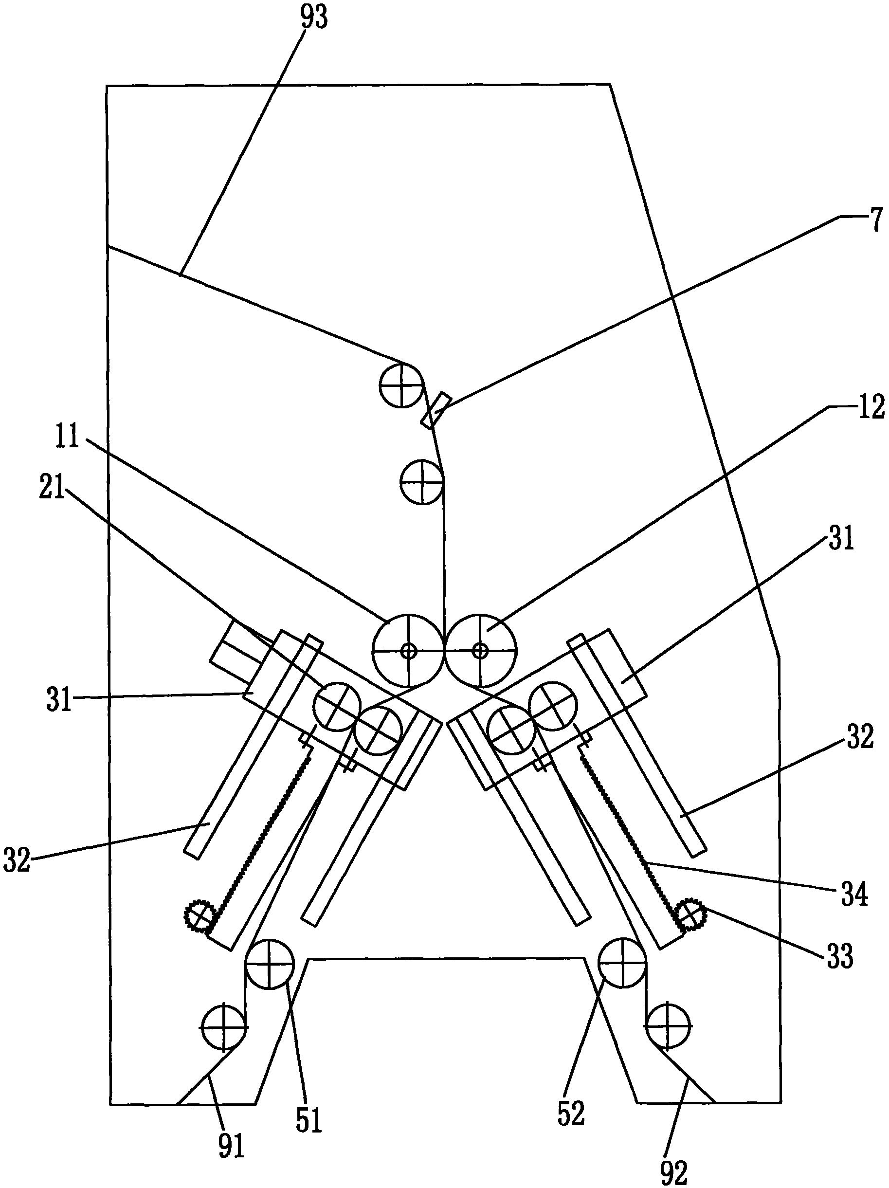
[0031] figure 1 , figure 2 , image 3 As shown, the self-adhesive film blown film production equipment includes a machine head 41, a herringbone splint 42, a film tube traction nip roller 6, a cutting knife 7, and two sets of film take-up mechanisms 81, 82 on the left and right, wherein the herringbone splint 42 Located above the machine head 41, the film tube traction nip roller 6 is located above the splint 42, and the left and right film coiling mechanisms 81, 82 are located below the cutting knife 7, and a pair of diaphragms are arranged below the cutting knife 7 Traction nip roller, the above-mentioned diaphragm traction nip roller comprises the first driving roller 11, the first driven roller 12, and the first driving roller 11, the first driven roller 12 are rubber rollers, the first driving roller 11 is formed by the first Driven by a motor; under the diaphragm traction nip roller, there are two pairs of split nip rollers symmetrically arranged left and right, and t...

Embodiment 2

[0038] In this embodiment, when the bracket moves to the upper end of the guide rail, the clearance distance between the splitting nip roller and the film traction nip roller is 10MM; and the angle formed between the line segment AB and the line segment CD is 60°. When the bracket moves to the lower end of the guide rail, the clearance distance between the splitting nip roller and the diaphragm traction nip roller is 400MM.

[0039] In addition, in the second embodiment, the first driving roller is a metal roller (left roller), and the first driven roller is a rubber roller (right roller). In each pair of splitting nip rollers, the second driving roller is a metal roller, the second driven roller is a silica gel roller, and the silica gel roller is located obliquely below the inner side of the metal roller.

[0040] All the other are the same as the first embodiment.

Embodiment 3

[0042] In this embodiment, when the bracket moves to the upper end of the guide rail, the clearance distance between the splitting nip roller and the film traction nip roller is 150 mm; and the angle formed between the line segment AB and the line segment CD is 178°. When the bracket moves to the lower end of the guide rail, the clearance distance between the splitting nip roller and the diaphragm traction nip roller is 850MM.

[0043] In addition, in the third embodiment, the first driving roller is a metal roller (right roller), and the first driven roller is a rubber roller (left roller). Both the second driving roller and the second driven roller are silicone rollers, one of which is located obliquely below the inner side of the other roller, the roller located obliquely below the inner side is the second driving roller, and the roller obliquely above the outer side is the second driven roller.

[0044] All the other are the same as the first embodiment.


PUM


Abstract

The invention provides self-adhesion membrane blowing production equipment. The equipment comprises a nose, a herringbone splint, membrane tube traction pinch rolls, a sectioning cutter, a left set of membrane coiling mechanism and a right set of membrane coiling mechanism, wherein the herringbone splint is positioned above the nose; a membrane tube traction pinch roll is positioned above the herringbone splint; the left set of membrane coiling mechanism and the right set of membrane coiling mechanism are positioned under the sectioning cutter; and a pair of membrane traction pinch rolls are arranged under the sectioning cutter, two pairs of opening pinch rollers are bilaterally and symmetrically arranged under the membrane traction pinch rolls, the left opening pinch rollers are positioned above the left membrane coiling mechanism, and the right opening pinch rollers are positioned above the right membrane coiling mechanism. The production equipment can smoothly coil the self-adhesion membrane, protects the self-adhesion membrane against wrinkle and fluctuation due to adhesion to the surfaces of a foam stabilizing device, the herringbone splint and the membrane tube traction pinch rolls, and ensures enough adhesion of the self-adhesion membrane finished product. The invention also provides a self-adhesion membrane blowing production method.

Description

technical field [0001] The invention belongs to the technical field of self-adhesive film production equipment and production methods, and in particular relates to a self-adhesive film blown film production equipment and a film blown production method. Background technique [0002] Self-adhesive film is also called self-adhesive protective film, and one of its surfaces is a sticky adhesive layer. Self-adhesive film is widely used in the surface protection of electrical and electronic equipment such as mobile phones and computers, as well as plastics, glass, building materials and other objects. The advantage of no residual adhesive substances on the surface. Self-adhesive film can be produced by gluing method, salivation method and co-extrusion blown film method. [0003] The existing self-adhesive film blown film production equipment includes a machine head, a herringbone splint, a film tube traction nip roller, a cutting knife, and two sets of film coiling mechanisms on ...

Claims


Application Information

Patent Timeline
Patent Type & Authority Applications(China)
IPC IPC(8): B29C55/28
Inventor 林梓生陈新辉李浩孙伟龙林永忠袁汉清
Owner GUANGDONG JINMING MACHINERY
Why Eureka
Try Eureka