Circuit board
A circuit board and release paper technology, which is applied in the direction of laminated printed circuit boards, printed circuits, printed circuits, etc., can solve the problems of reducing the number of circuit boards and increasing costs
Inactive Publication Date: 2011-01-05
SUMITOMO BAKELITE CO LTD
View PDF1 Cites 0 Cited by
- Summary
- Abstract
- Description
- Claims
- Application Information
AI Technical Summary
Problems solved by technology
But when Figure 7 In the circuit board of the shown structure, the part of the pull tab 2p used to form a part of the release paper 2 protrudes outward from the surface of the circuit board 1, so in appearance, the protruding part also becomes a circuit board. As a result, the number of circuit boards that can be separated from the workpiece substrate is reduced, which will become an important cause of cost increase
Method used
View moreImage
Smart ImageViewing Examples
Examples
Embodiment Construction
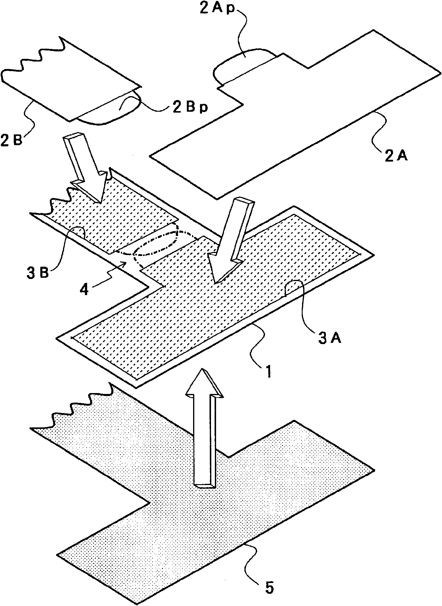
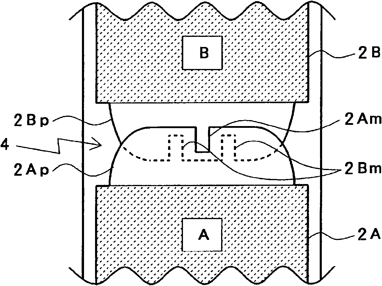
[0037] Next, a circuit board according to the present invention will be described based on the illustrated embodiments. figure 1 is a plan view showing the basic structure of the circuit board involved in the present invention, figure 2 A preferred laminated structure example thereof is shown by a perspective view.
Login to View More PUM
 Abstract
Release papers (2A,2B) are stuck via adhesive layers (3A,3B) onto one major surface of a circuit board (1) consisting of a flexible multilayer substrate in a fashion such that the adhesive layers are covered. A nonadhesive area (4) devoid of any adhesive layer is provided on the surface of the circuit board between release papers (2A,2B) adjacent to each other. End portions of the release papers (2A,2B) positioned on the nonadhesive area (4) are provided with pull tabs (2Ap,2Bp) for detachment of the release papers. Preferably, the individual pull tabs are provided so as to be opposite to each other on the nonadhesive area (4) and so that the distal end portions of the pull tabs overlap each other on the surface of the circuit board. Accordingly, the sequence of detachment of release papers from the surface of the circuit board can be grasped.
Description
technical field [0001] The present invention relates to a circuit board having a structure in which an adhesive layer is covered with a release paper. Background technique [0002] With the high performance and light weight and thinner requirements of electronic equipment in recent years, the degree of high-density integration of electronic components is increasing, and the degree of high-density mounting of electronic components is also increasing. Along with this, the degree of miniaturization and multi-pin (semiconductor package) used in the above-mentioned electronic equipment is further deepened than before. Therefore, the degree of multilayering of circuit boards (printed wiring boards) for mounting the above-mentioned semiconductor packages and the like is increasing, and flexible multilayer circuit boards are often used for such circuit boards. In addition, a multilayer circuit board on which the above-mentioned semiconductor package and the like are mounted is arra...
Claims
Login to View More Application Information
Patent Timeline
 Patent Type & Authority Applications(China)
IPC IPC(8): H05K1/02B32B15/08
CPCH05K3/386H05K1/0393H05K2203/0264H05K2201/09109H05K3/0058H05K2203/0271
Inventor 桥户宏明三富政利
Owner SUMITOMO BAKELITE CO LTD
Features
- Generate Ideas
- Intellectual Property
- Life Sciences
- Materials
- Tech Scout
- Unparalleled Data Quality
- Higher Quality Content
- 60% Fewer Hallucinations
Learn More Browse by: Latest US Patents, China's latest patents, Technical Efficacy Thesaurus, Application Domain, Technology Topic, Popular Technical Reports.
© 2025 PatSnap. All rights reserved.Legal|Privacy policy|Modern Slavery Act Transparency Statement|Sitemap|About US| Contact US: help@patsnap.com


