
Network for dynamically suppressing power frequency interference of power transmission line

A technology for line workers and transmission lines, applied in the field of power transmission and transformation equipment testing facilities, can solve the problems of low stability of test results, low data reliability, damage to test instruments, etc., to achieve stable and accurate test results, and the ability to suppress interference. , the effect of eliminating the influence

Inactive Publication Date: 2011-01-05
WUHAN DAYANG YITIAN TECH
View PDF0 Cites 11 Cited by
  • Summary
  • Abstract
  • Description
  • Claims
  • Application Information

AI Technical Summary

Problems solved by technology

[0003] The development of the power grid is restricted by the land corridor, and the density is getting higher and higher. Double-circuit or multi-circuit lines on the same tower have become the norm. The coupling between lines has reached an unprecedented level. The electromagnetic coupling induced interference current can reach 60-80A, high-quality The demand for power supply makes it unrealistic to reduce the interference level by power failure during the test
[0004] In traditional test facilities, the method of phase inversion or phase shifting is used to eliminate the influence of power frequency interference on the test results, but when the amplitude and phase of the interference change, the stability of the test results is low, and the reliability of the data is not high , At the same time, there are great potential safety hazards, and the damage to the test instrument often occurs during the test, which verifies the limitation of the method of changing the phase to suppress the influence of interference

Method used


Image

  • Network for dynamically suppressing power frequency interference of power transmission line
  • Network for dynamically suppressing power frequency interference of power transmission line

Examples


Embodiment Construction

[0019] Description will be made below in conjunction with the accompanying drawings.

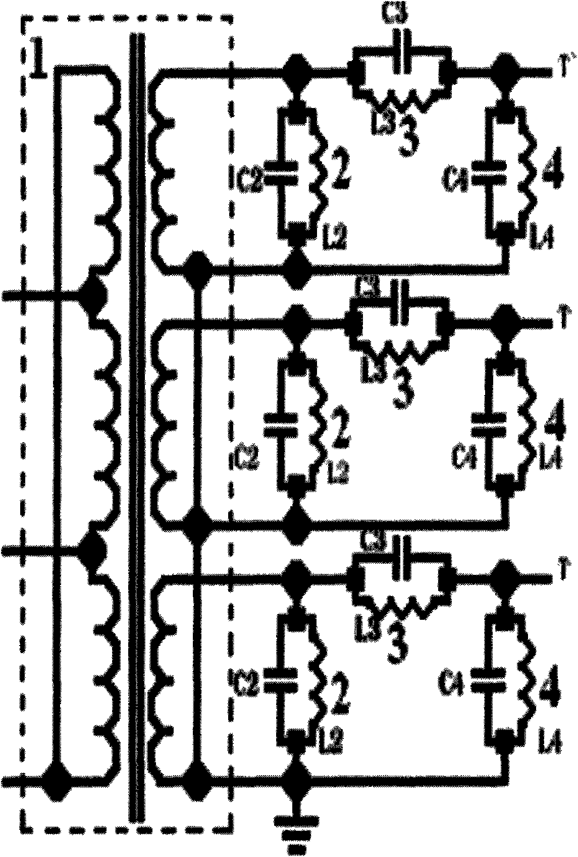
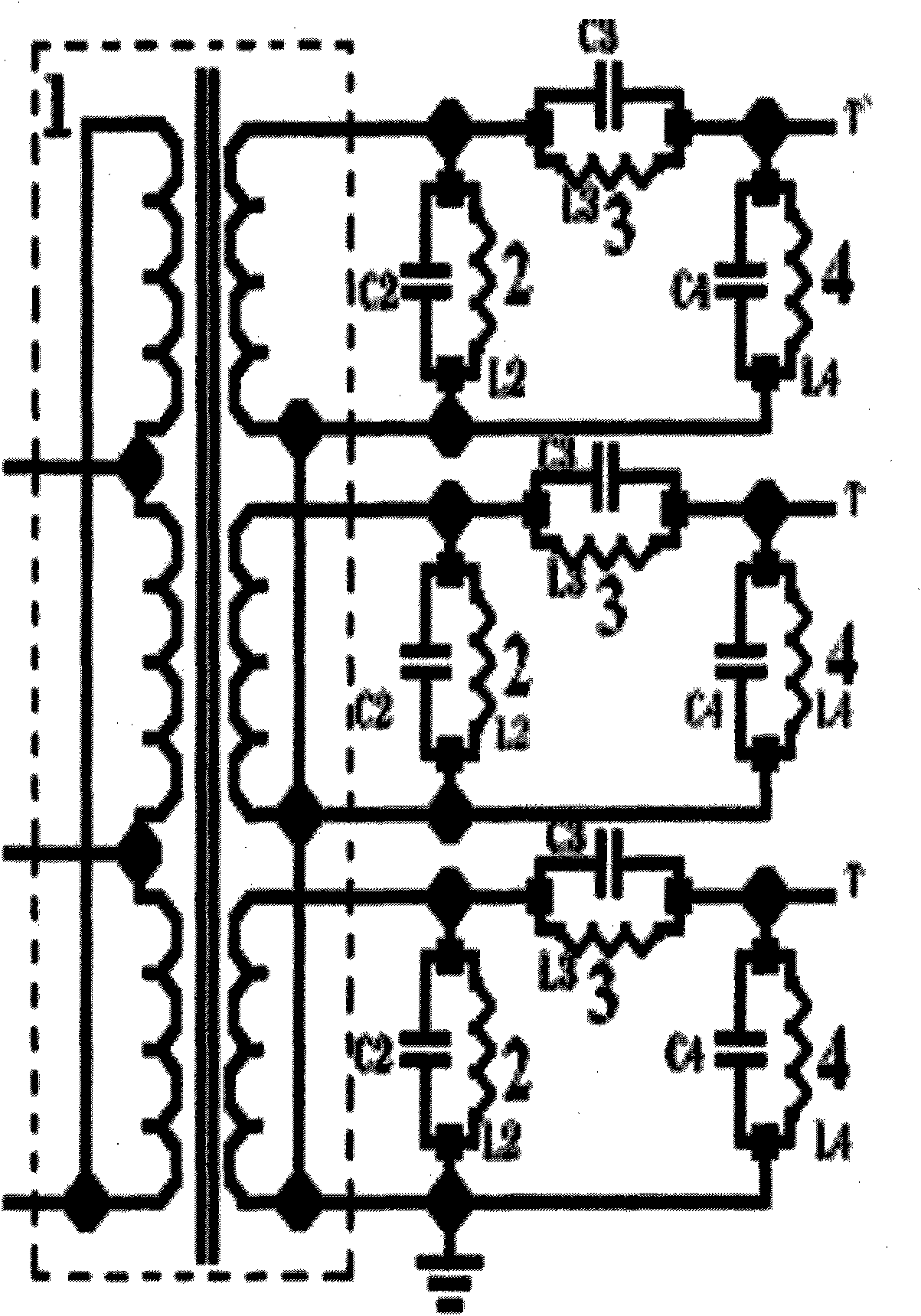
[0020] In Fig. 1, the present invention is composed of an isolated three-phase transformer 1, a filter impedance 2, an interference current suppression impedance 3 and an interference voltage discharge impedance 4, the isolated three-phase transformer 1 is a Δ / Y connection, and the filter impedance 2 is connected in parallel to the isolated three-phase transformer. Phase transformer 1 secondary winding, one end of the interference current suppression impedance 3 is connected to the non-common end of the secondary winding of the isolated three-phase transformer, the other end of the interference current suppression impedance 3 is connected to one end of the filter impedance 2 and the terminal T of the line under test, The interference voltage discharge impedance 4 is connected to the other end of the filter impedance 2 and the common end of the secondary winding of the isolated three-phase tra...


PUM


Abstract

The invention relates to a network for dynamically suppressing power frequency interference of a power transmission line, which belongs to test facilities for electric transmission and transformation equipment. The network is characterized by consisting of an isolation three-phase transformer, a filtering impedor, an interference current suppressing impedor and an interference voltage releasing impedor, wherein the isolation three-phase transformer adopts delta / Y connection; the filtering impedor is connected in parallel with a secondary winding of the isolation three-phase transformer; one end of the interference current suppressing impedor is connected with a non-public end of the secondary winding of the isolation three-phase transformer while the other end is connected with one end of the filtering impedor and a tested circuit end; the interference voltage releasing impedor and the other end of the filtering impedor are connected with a public end of the secondary winding of the isolation three-phase transformer; the filtering impedor, the interference current suppressing impedor and the interference voltage releasing impedor consist of a capacitive reactor and an inductive reactor which are connected in parallel respectively; the filtering impedor and the interference voltage releasing impedor are capacitive; and the interference current suppressing impedor is inductive. The problems of low test result stability, low data reliability and high potential safety hazard of the conventional test facility are solved and the network is used for testing a power frequency parameter of the power transmission line by a pilot frequency method.

Description

technical field [0001] The invention relates to a dynamic suppression network for power frequency interference of power transmission lines, which is used for power frequency parameter testing of power transmission lines by different frequency methods, and belongs to power transmission and transformation equipment testing facilities. Background technique [0002] The development of the power system has made the scale of the power grid larger and larger, the structure more and more complex, and the requirements for the reliability of system protection are also getting higher and higher. It is necessary to provide more accurate system parameters for the protection setting as a calculation basis, and at the same time the power grid structure optimization More accurate parameters of each main component of the power system are also required. The positive-sequence parameters and zero-sequence parameters of high-voltage transmission lines, as well as the mutual impedance and couplin...

Claims


Application Information

Patent Timeline
IPC IPC(8): H02J3/01G01R1/00G01R31/00
CPCY02E40/40
Inventor 范毅程澜
Owner WUHAN DAYANG YITIAN TECH
Learn More