Automatic positioning method for drill rod end straightening

An automatic positioning and drill pipe technology, applied in the control using feedback, program control in sequence/logic controller, electrical program control, etc., can solve the problems of low positioning accuracy, poor straightness and poor consistency of straightening products , to achieve the effect of improved safety and improved positioning accuracy

Active Publication Date: 2012-05-30
BAOSHAN IRON & STEEL CO LTD +1
View PDF0 Cites 0 Cited by
  • Summary
  • Abstract
  • Description
  • Claims
  • Application Information

AI Technical Summary

Problems solved by technology

[0003] The existing oil well drill pipe pressure straightening process adopts manual straightening, and the positioning of the axial and circumferential phases is completely based on visual inspection and manual positioning. The positioning accuracy is low, the consistency is poor, the labor intensity is high, the efficiency is low, and the straightness of the straightened product is poor.

Method used


Image

  • Automatic positioning method for drill rod end straightening
  • Automatic positioning method for drill rod end straightening
  • Automatic positioning method for drill rod end straightening

Examples


Embodiment Construction

[0018] The present invention will be further described below in conjunction with the accompanying drawings and specific embodiments.

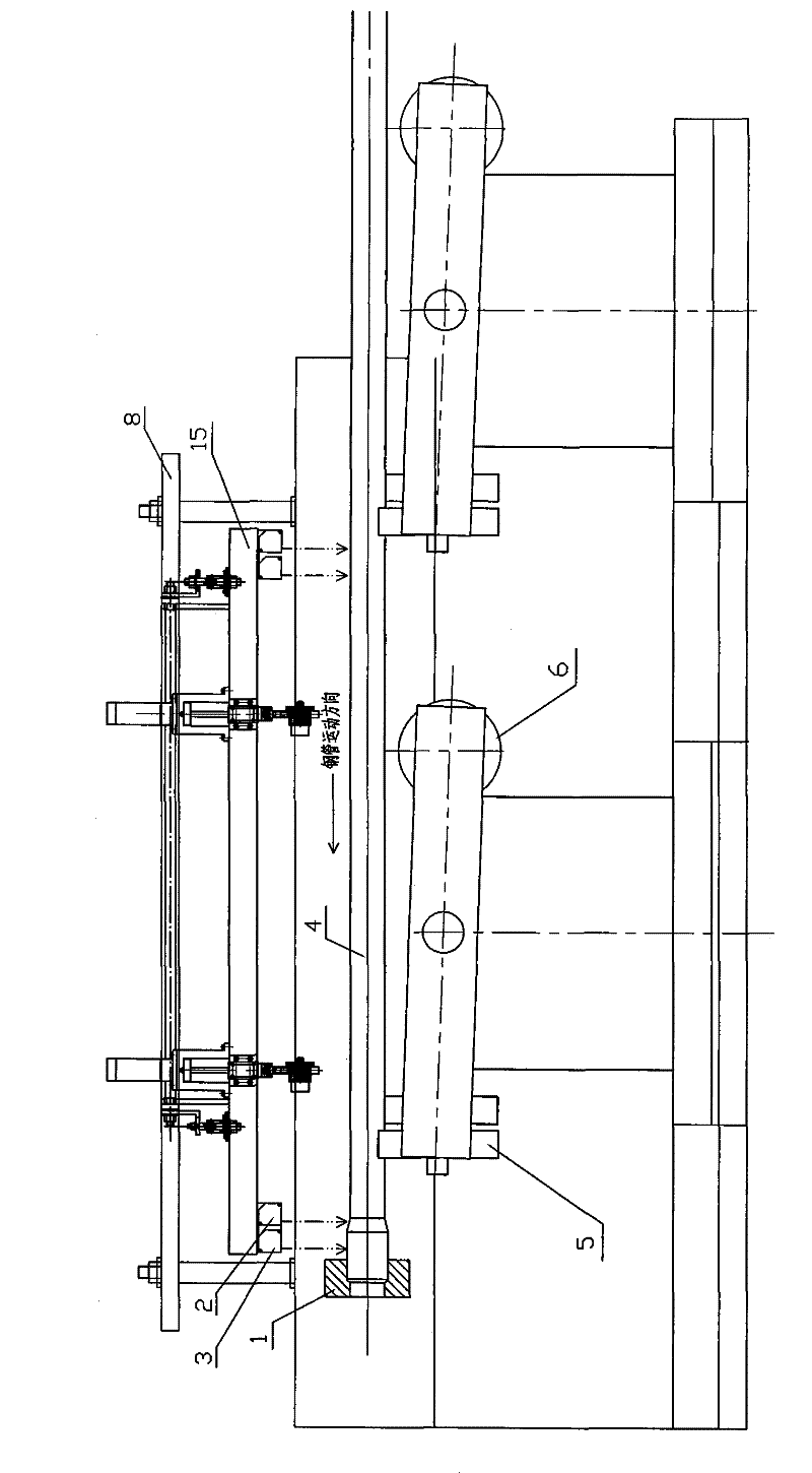
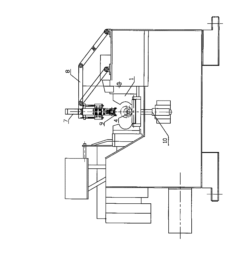
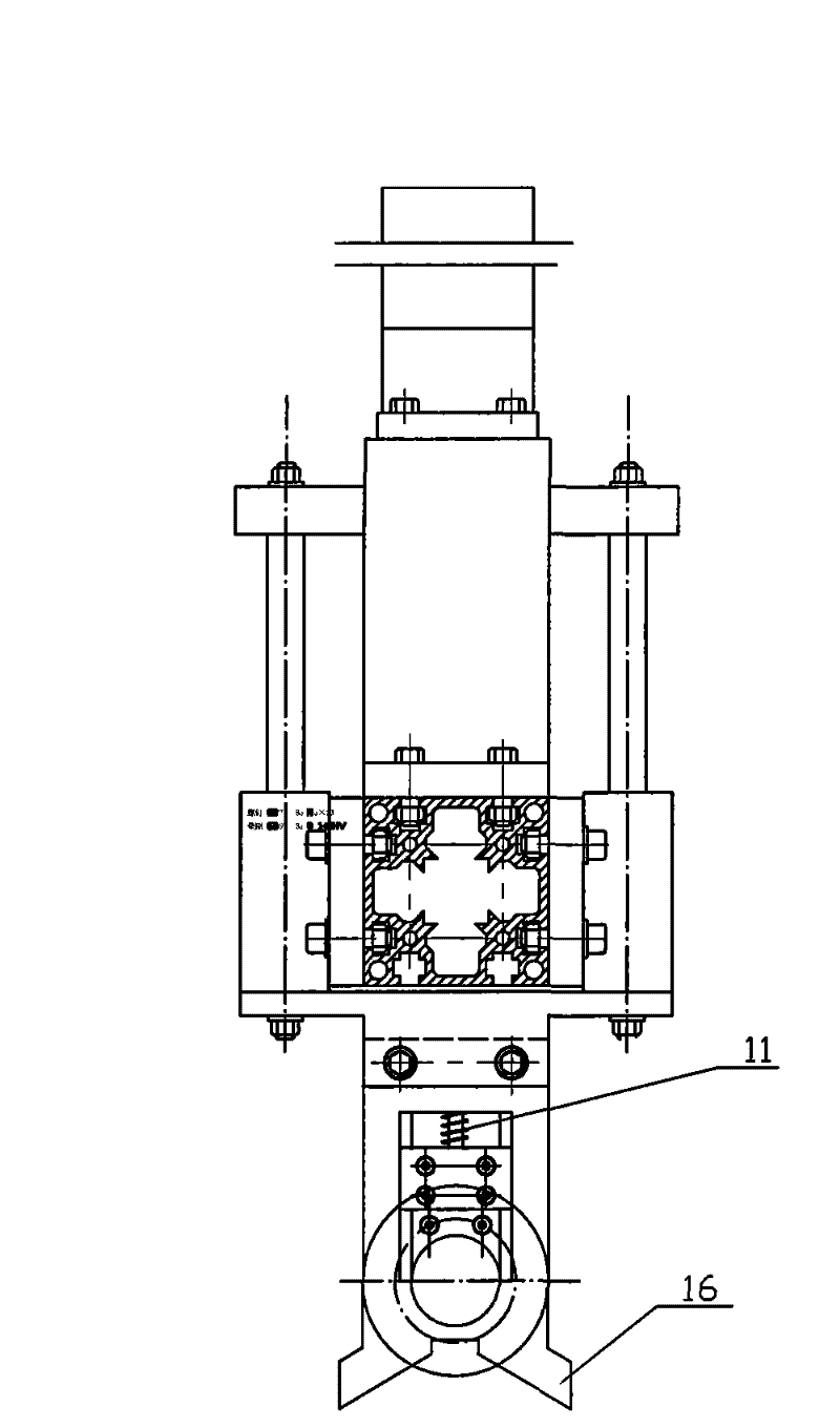
[0019] see figure 1 , figure 2 , image 3 , Figure 4 , an automatic positioning method for straightening the end of a drill pipe, is to perform axial and circumferential straightening phase positioning control at the straightening position, wherein:

[0020] Axis control: see figure 1 ,

[0021] The driving system controls the axial conveying roller table 6, and transports the drill pipe 4 from right to left to the straightening area on the conveying roller table, so that the straightening blind area of ​​the drill pipe 4 is fully exposed to the detection field of view of the displacement sensors 2 and 3, and the displacement Sensors 2 and 3 are installed on the measuring frame 15 above the conveying roller table, and the displacement sensors 2 and 3 detect the axial position of the drill pipe 4 and feed back to the controller to output ...


PUM


Abstract

The invention discloses an automatic positioning method for drill rod end straightening. The method comprises axial and circumferential straightening phase positioning control at a straightening position, wherein the axial control comprises that: the axial position, detected by a displacement sensor, of a drill rod is fed back to a controller output control driving system to reduce the speed of aconveying rollway; and the drill rod is positioned in the clamp by adopting a step clamp. The circumferential control comprises that: after the drill rod reaches a detection station, a rotary bracketis lifted so that the drill rod is supported by a rotary wheel; a rubber roller above the drill rod presses the outside the drill rod, and a rubber roller shaft is provided with an angle coder; and the angle coder is passively rotated through the rubber roller, and the rotating angle displacement of the drill rod can be determined according to the diameter of the drill rod and the fixed diameter of the rubber roller and is fed back to a controller so as to finish automatic positioning. The method improves the positioning precision of drill rod end straightening, shortens the auxiliary time for detection and straightening, and obviously improves the straightening efficiency and the straightening precision.

Description

technical field [0001] The invention relates to a method for automatically positioning the axial and circumferential phases of a drill rod during the straightening process of the end of the drill rod, and belongs to the technical field of automatic control. Background technique [0002] Oil well drill pipe is a key component that drives the drill bit to rapidly advance deep into the formation during oil exploration and production, so there is a high requirement for its straightness. Due to the shape characteristics of oil well drill pipe with large length-to-diameter ratio, thin pipe wall, and upsetting at both ends, it is necessary to perform pressure straightening in the blind straightening area where the straightness of the end is out of tolerance during the processing process. In order to complete the pressure straightening in the straightening blind zone, it is necessary to realize the precise positioning of the drill pipe in the axial direction and the precise position...

Claims


Application Information

Patent Timeline
Patent Type & Authority Patents(China)
IPC IPC(8): G05D3/12G05B19/04B21D3/00
Inventor 刘春旭胡德金朱世忠许黎明刘茂生高展魏臣隽董长富
Owner BAOSHAN IRON & STEEL CO LTD
Why Eureka
Try Eureka