Pneumatic braking jig dyeing machine of gear swing-arm single motor

A pneumatic brake, single-motor technology, applied in textile processing machine accessories, liquid/gas/vapor open-width fabric processing, textiles and papermaking, etc. emission reduction and other issues

Inactive Publication Date: 2011-01-05
ZAOZHUANG FUYUAN ENVIRONMENTAL PROTECTION & ENERGY SAVING MACHINERY MFG CO LTD
View PDF5 Cites 0 Cited by
  • Summary
  • Abstract
  • Description
  • Claims
  • Application Information

AI Technical Summary

Problems solved by technology

There are two disadvantages: one is that the investment in the motor and reducer is increased, which increases the purchase cost of the equipment; the other is that the reducer and the cloth roll are directly connected to the torque operation, which increases the power of the motor, which does not meet the national energy saving and emission reduction requirements. policy

Method used


Image

  • Pneumatic braking jig dyeing machine of gear swing-arm single motor
  • Pneumatic braking jig dyeing machine of gear swing-arm single motor
  • Pneumatic braking jig dyeing machine of gear swing-arm single motor

Examples


Embodiment Construction

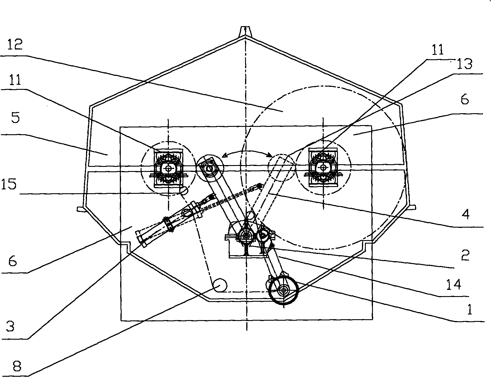
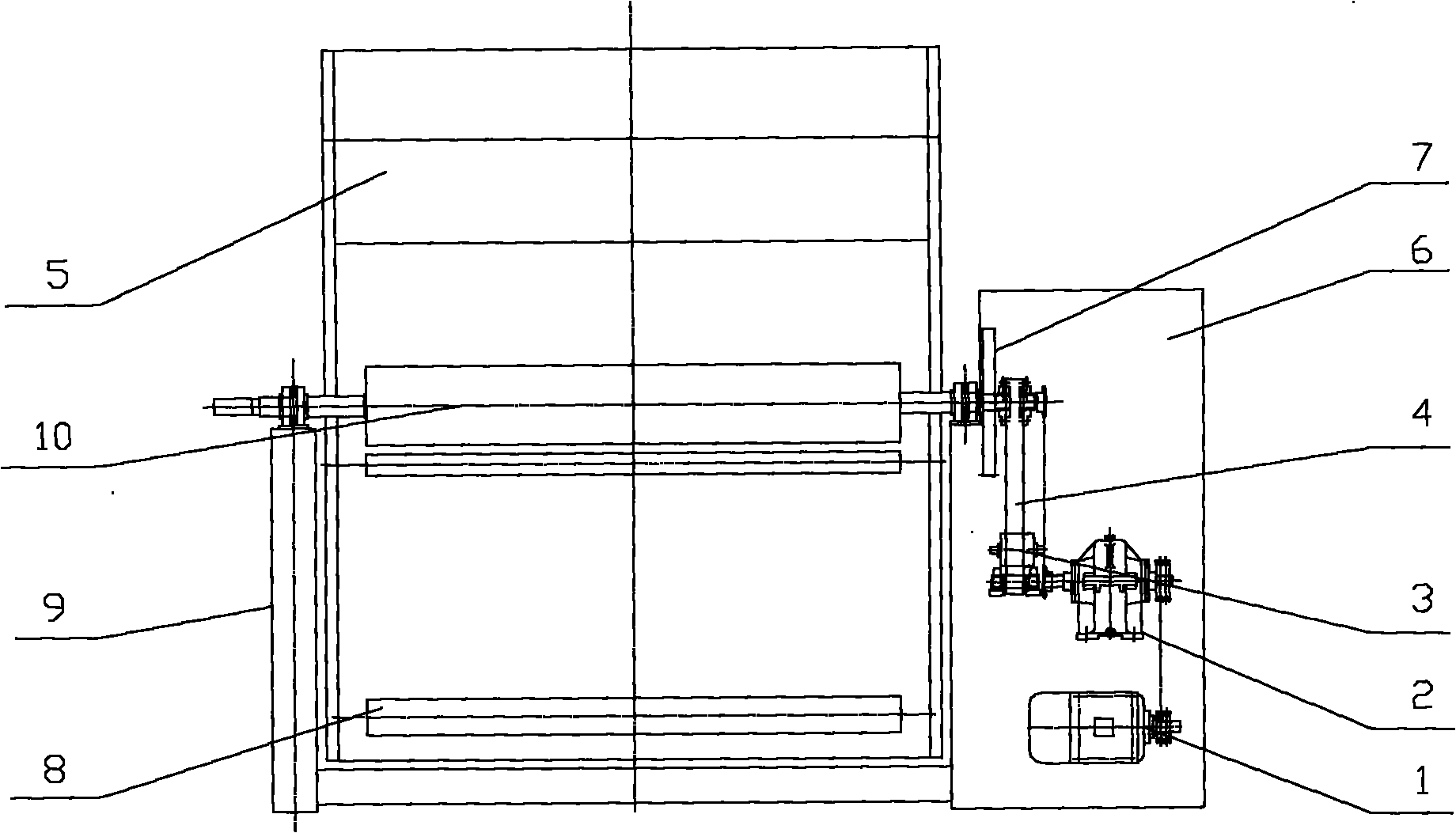
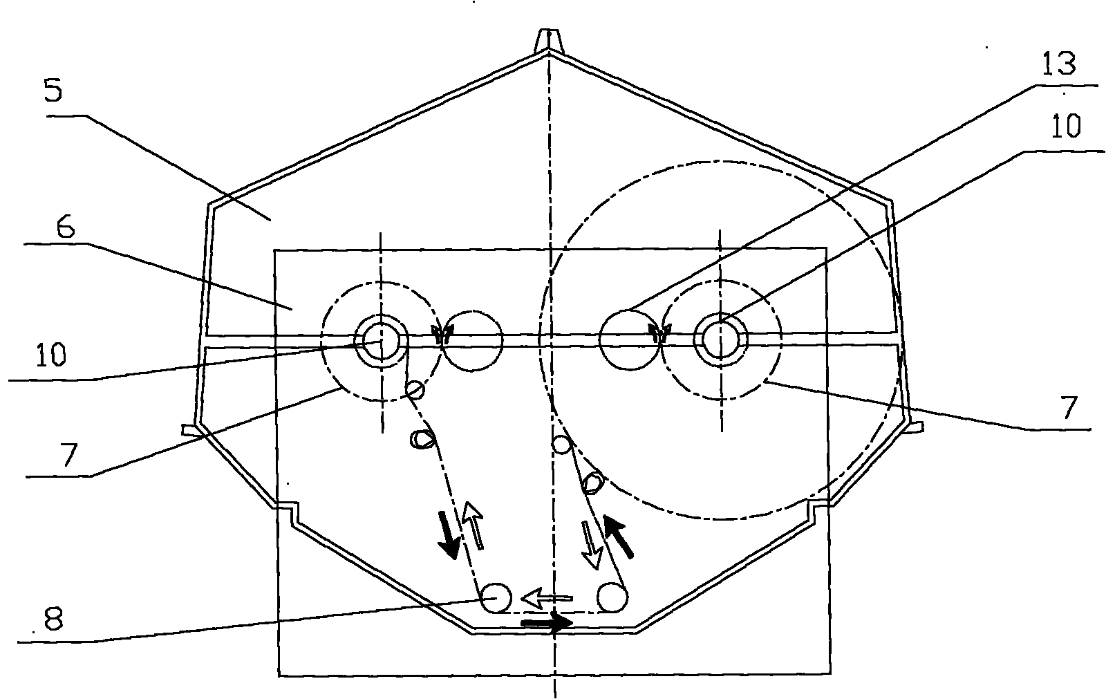
[0008] The invention as figure 1 As shown, by the dyeing vat 5, the head box 6, the pneumatic brake device 11, the fabric guide roller 8, the tension frame 15, the main drive swing gear 13, the transmission arm 4, the cylinder 3, the reducer 2, the motor 1, the transmission mechanism 14, Two passive large gears 7, frame 9, figure 2 Shown, the left cloth roll 10, the right cloth roll 10, image 3 composition as shown. The motor 1 is decelerated by the transmission mechanism 14 connected to the reducer 2; as figure 1 , 2 As shown, the lower end of the transmission support arm 4 is assembled on the output shaft of the reducer, such as figure 2 , 3 As shown, the main drive swing gear 13 is installed on the upper end of the transmission support arm, and the passive large gear 7 is respectively installed on the one end shaft 10 of the left and right cloth rolls. The cylinder 3 is connected with the transmission support arm 4, and the cylinder 3 has the function of traction an...


PUM


Abstract

The invention provides a pneumatic braking jig dyeing machine of a gear swing-arm single motor, which relates to a jig dyeing machine in the technical field of a weaving and dyeing machine. The invention aims at designing a novel driving and braking mechanism which has the advantages of simpler structure, smooth operation and convenient maintenance, reduced auxiliary investment of a device and motor power and energy saving. Disclosed as a picture 1, a main driving and swinging gear 13 is arranged at the upper end of a transmission support arm 4, and driven large gears 7 are respectively arranged on end shafts 10 of a left cloth roller and a right cloth roller. Disclosed as a picture 2, the repeated alternate operation function of the left and the right cloth rollers 10 is realized, and the shaft ends of the two cloth rollers are provided with a pneumatic braking device 11 which is formed by combining a pneumatic brake 11 and a tension brake 11, wherein the pneumatic brake 11 is used for quickly parking the left cloth roller 10 and the right cloth roller 10 when steering, and the tension brake 11 is used for preventing the relaxation of fabrics 12 in normal operation and is capable of increasing proper constant tension for the fabrics 12. When an air cylinder 3 works, the transmission support arm 4 is driven to swing, the main driving and swinging gear 13 is sequentially in tight contact with the left and the right cloth rollers 10, the left and the right cloth rollers 10 are used for alternately winding the fabrics 12 to rotate, and the fabrics 12 is smoothly operated under the function of the tension brake 11. Due to the adoption of the novel driving structure, the device structure is very simple and compact, the manufacturing cost of the device is reduced, and more importantly, large numbers of energy sources can be saved for users, production cost is reduced and economic benefit is increased.

Description

technical field [0001] The invention relates to the technical field of textile printing and dyeing machinery. Especially suitable for jiggers for open-width bleaching and dyeing in the textile printing and dyeing industry. Background technique [0002] At present, the existing jiggers on the market have a small footprint, are suitable for trial production and production of multiple varieties and small batches, meet the current market demand, and are welcomed by printing and dyeing manufacturers. However, at present, most manufacturers of dyeing machines at home and abroad adopt a double-motor structure. There are two disadvantages: one is that the investment in the motor and reducer is increased, which increases the purchase cost of the equipment; the other is that the reducer and the cloth roll are directly connected to the torque operation, which increases the power of the motor, which does not meet the national energy saving and emission reduction requirements. policy. ...

Claims


Application Information

Patent Timeline
IPC IPC(8): D06B3/32D06B23/00
Inventor 孙有福
Owner ZAOZHUANG FUYUAN ENVIRONMENTAL PROTECTION & ENERGY SAVING MACHINERY MFG CO LTD
Why Eureka
Try Eureka