
Method for installing tail shaft on 10,000DWT roll-on-roll-off ship as well as dedicated roller tool

An installation method and technology of roller tools, which are used in manufacturing tools, metal processing, hand-held tools, etc., can solve problems such as difficulty in installation and positioning, adjustment of tail shafts, and inability to lift tail shafts. The effect of shortening the installation period

Inactive Publication Date: 2011-01-05
CSC JINLING SHIPYARD
View PDF0 Cites 7 Cited by
  • Summary
  • Abstract
  • Description
  • Claims
  • Application Information

AI Technical Summary

Problems solved by technology

[0002] At present, the length of the tail shaft of the 10,000-ton ro-ro ship is generally more than 20 meters, and the dead weight is more than 35 tons. The fit clearance of the bearing is only 0.9 mm, and it is very difficult to install the stern shaft with a length of more than 20 meters into the stern shaft tube pre-installed with three bearings, mainly because the front end of the tail shaft crosses the middle bearing and the When there is still a certain distance, due to the weight of the tail shaft itself, the tail shaft bends and sags, causing the front end of the tail shaft to collide with the inner wall of the stern shaft tube and cannot continue to move forward. At this time, the center of gravity of the tail shaft is very close to the tail bearing, so it cannot move forward. To adjust the angle and center line of the stern shaft outside the stern tube, it must be adjusted at the front end of the stern shaft inside the stern tube, and the wall thickness and length of the common tool lifting beam are affected by the space of the stern tube and the hull engine room. Raised the front end of the tail shaft, so had to be addressed with a new tail shaft installation method and tooling

Method used


Image

  • Method for installing tail shaft on 10,000DWT roll-on-roll-off ship as well as dedicated roller tool
  • Method for installing tail shaft on 10,000DWT roll-on-roll-off ship as well as dedicated roller tool
  • Method for installing tail shaft on 10,000DWT roll-on-roll-off ship as well as dedicated roller tool

Examples


specific Embodiment approach

[0019] This example figure 1 , figure 2 As shown, a tail shaft installation method of a 10,000-ton ro-ro ship adopts the following installation steps. Two first trolleys 5 and second trolleys 6 that can move on the guide rails are set. The height of the trolleys can be adjusted by the hydraulic pressure on the trolleys. The top is adjusted, and the trolley is controlled by a motor. An ingot iron 8-1, 8-2 is respectively arranged on the trolley to support and radially locate the tail shaft 9, and the tail shaft 9 is placed on two movable dollies, the ingot iron 8-1, 8-2, the tail shaft propeller hub 10 of the tail shaft 9 is placed on the ingot iron 8-1 of the second trolley 6 at the rear, and the distance between the two cars is 13 meters apart to ensure that the center of gravity of the tail shaft 9 falls on the center of the two cars. In the middle, adjust the distance between the ingot iron 8-2 of the first trolley 5 and the horizontal guide rail 7 to be 4.11 meters, and ...


PUM


Abstract

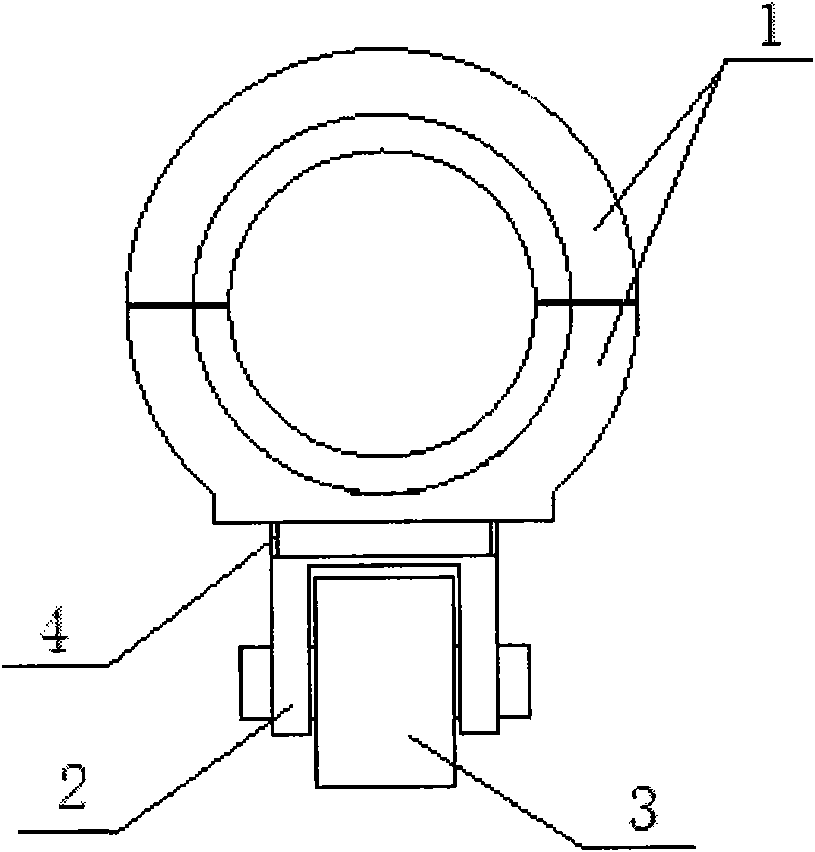
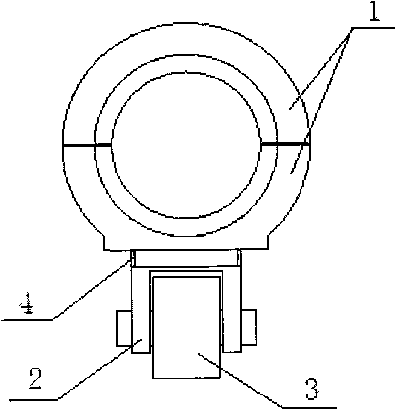
The invention provides a method for installing a tail shaft on a 10,000DWT roll-on-roll-off ship as well as a dedicated roller tool. The method comprises the following steps: threading the tail shaft of the roll-on-roll-off ship in a tail shaft tube equipped with a front bearing, a middle bearing and a rear bearing in a safe and rapid manner. The dedicated roller tool comprises haff fasteners, a support and a roller, wherein one end of the support is mounted on one haff fastener via threads, and the roller is mounted at the other end thereof. By achieving the safe and rapid installation of the tail shaft on the 10,000DWT roll-on-roll-off ship, the invention can shorten the installation period; meanwhile, by using the dedicated roller tool, the invention can facilitate the installation and adjustment of the tail shaft and prevent the components in the tail shaft tube from being damaged.

Description

technical field [0001] The invention relates to a stern shaft installation method and a tool, in particular to a 10,000-ton ro-ro ship stern shaft installation method and a special roller tool. Background technique [0002] At present, the length of the tail shaft of the 10,000-ton ro-ro ship is generally more than 20 meters, and the dead weight is more than 35 tons. The fit clearance of the bearing is only 0.9 mm, and it is very difficult to install the stern shaft with a length of more than 20 meters into the stern shaft tube pre-installed with three bearings, mainly because the front end of the tail shaft crosses the middle bearing and the When there is still a certain distance, due to the weight of the tail shaft itself, the tail shaft bends and sags, causing the front end of the tail shaft to collide with the inner wall of the stern shaft tube and cannot continue to move forward. At this time, the center of gravity of the tail shaft is very close to the tail bearing, an...

Claims


Application Information

Patent Timeline
Patent Type & Authority Applications(China)
IPC IPC(8): B23P11/00B25B27/00
Inventor 陈晓星张志定李军胡明奇
Owner CSC JINLING SHIPYARD
Learn More