
Illumination means

A component and organic technology, applied in the field of lighting components, to achieve the effects of reducing production costs, increasing production volume, and high brightness

Active Publication Date: 2013-04-24
EMDE PROJECTS GMBH
View PDF2 Cites 0 Cited by
  • Summary
  • Abstract
  • Description
  • Claims
  • Application Information

AI Technical Summary

Problems solved by technology

The disadvantage of this known OLED is that, because the manufacturer uses the OLED as a planar sheet light source on a rectangular carrier, the user is limited in advance to using only this light source in the subsequent use process.
Therefore, bendable substrates also have the drawbacks described above

Method used


Image

  • Illumination means
  • Illumination means
  • Illumination means

Examples


Embodiment Construction

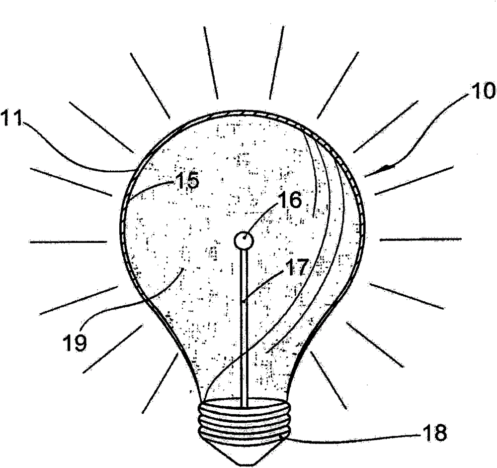
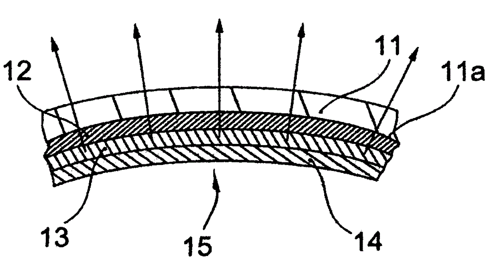
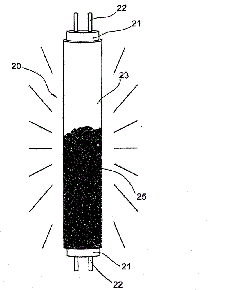
[0040] figure 1 A schematic diagram of a lighting component 10 according to the invention is shown in , which in principle has the outer geometry of a conventional incandescent lamp. The lighting component has a hollow body 11 made of glass, which is partially spherical in shape (rod-shaped or pear-shaped), and which is the carrier of a multilayer coating structure 15 composed of light-emitting diodes. The first electrode 12 is in the figure 1 In an embodiment variant of the coating structure 15, the first electrode 12 also has an emissive layer that emits light when excited (see figure 2 ). This first electrode 12 is electrically connected to one another with a first electrical contact, not shown here, which is located, for example, in the region of the base 18 of the lighting member. This base 18 is designed, for example, as the screw base of a conventional incandescent lamp. The second electrode of the OLED structure is as figure 1 An almost point-shaped electrode 16 ...


PUM


Abstract

The present invention relates to illumination means (10) based on organic light diodes (OLED), having a layer arrangement (15) with at least one organic light-emitting diode layer (OLED layer), and at least one anode layer and one cathode layer on a carrier, and contact means (22) for the electrical contact of the electrode layers. According to the invention, the OLED layer and at least one electrode layer are attached to the inner side of a dimensionally stable rotation surgace serving as the carrier. According to the invention, the inner surface of a substantially or entirely closed hollow body (11) made of glass, plastic, or another light-transmissice material can serve as a carrier. The invention creates a novel illumination means (10) based on organic light diodes, having a shape that is compatible with a conventional light bulb or fluorescent lamp, and consequently can be exchanged for the same.

Description

technical field [0001] The invention relates to a lighting component based on an organic light-emitting diode (OLED), which has at least one organic light-emitting coating (OLED layer) and at least one positive and / or negative layer on or in a carrier and Contact member for electrical contacting of electrode layers. The invention also relates to a method for producing a lighting member of the type described above. Background technique [0002] For some time, OLEDs developed in recent years for use as lighting components have been on the rise in practical use due to their steadily increasing light yield and efficiency. So, for example, an OLED with a power of 35 Im / Watt or even more than 60 Im / Watt can achieve a brightness of 1000 cd / m2 and a lifetime of 100.000 hours. OLEDs are applied in the form of very thin layers (for example only a few nm) onto a flat support. Flake-shaped rectangular substrates, for example glass flakes, may be used as supports. However, OLED-based...

Claims


Application Information

Patent Timeline
Patent Type & Authority Patents(China)
IPC IPC(8): F21K7/00F21K99/00F21Y101/00
CPCF21K9/135F21V3/00F21Y2105/008H01L2251/5361F21Y2103/003Y02B20/36F21K9/17F21Y2101/02Y02B20/386F21Y2105/00F21K9/232F21K9/27F21Y2103/10F21Y2115/10F21Y2115/15F21K9/66Y02B20/30H10K50/805H10K50/85H10K50/84
Inventor 托马斯·埃姆德
Owner EMDE PROJECTS GMBH
Learn More