
Roadway surrounding rock separation layer displacement monitor

A technology for displacement monitoring and rock separation, applied in instruments, measuring devices, optical devices, etc., can solve the problems of complex manufacturing process and structure, easy deformation and accuracy of soft pull wires, etc. The effect of simple craftsmanship and structure

Inactive Publication Date: 2010-12-29
安里千
View PDF4 Cites 13 Cited by
  • Summary
  • Abstract
  • Description
  • Claims
  • Application Information

AI Technical Summary

Problems solved by technology

However, the rock formation displacement monitor made according to the above-mentioned patent has the following disadvantages: two grating discs are installed on an axis in the housing, and two sections of the upper and lower pull wires need to be drawn out from the housing to transmit displacement and retraction. Tight pull wire, the manufacturing process and structure are relatively complicated, and at the same time, the accuracy of displacement detection is affected by the easy deformation of the soft pull wire

Method used


Image

  • Roadway surrounding rock separation layer displacement monitor
  • Roadway surrounding rock separation layer displacement monitor
  • Roadway surrounding rock separation layer displacement monitor

Examples


Embodiment 1

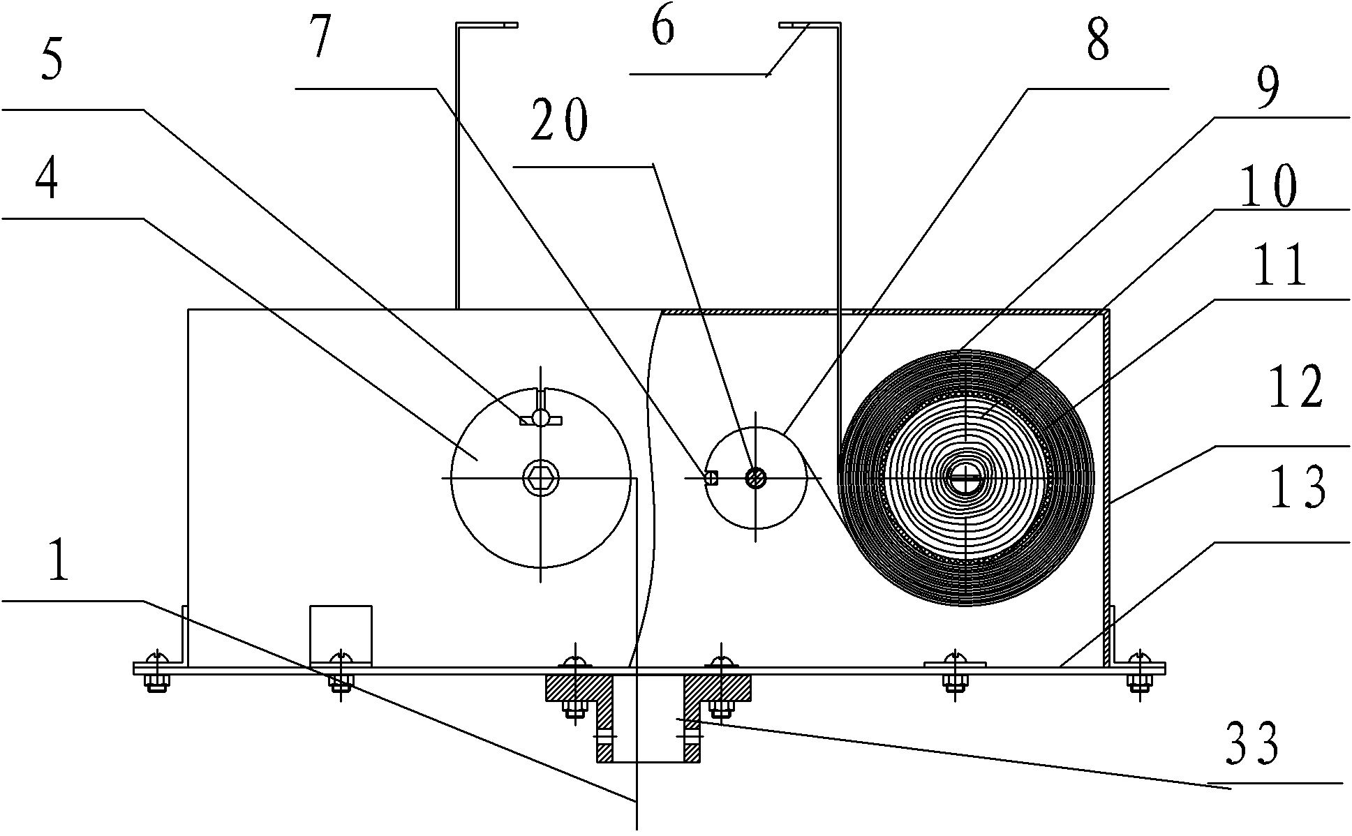
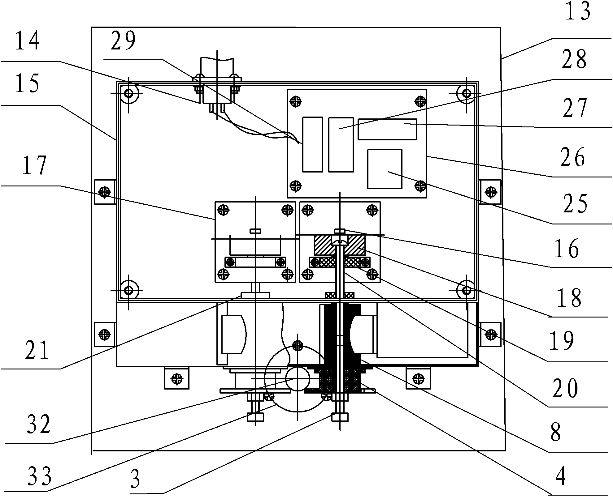
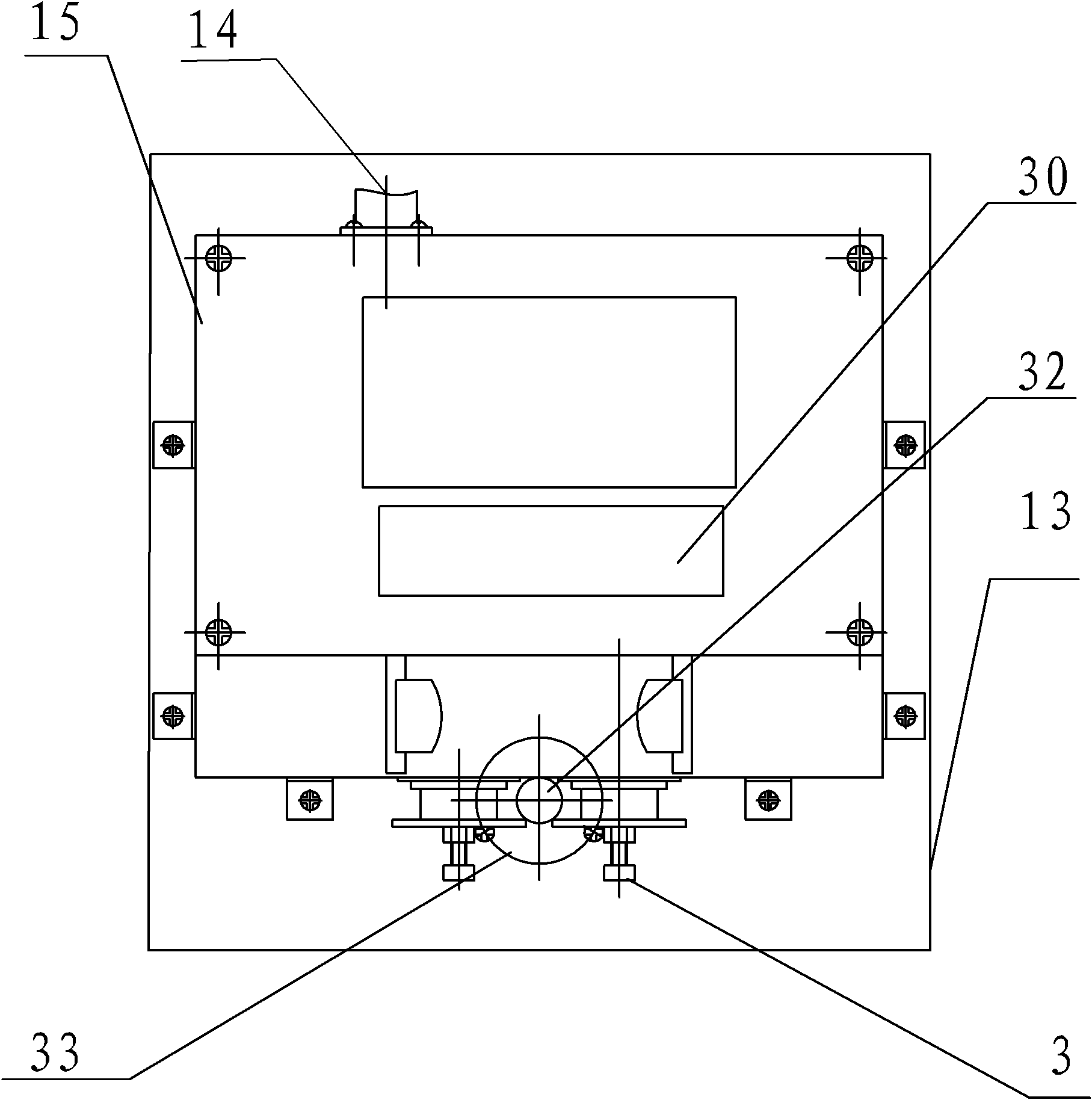
[0027] refer to figure 1 and figure 2 , The present invention includes a casing 15 and a protective plate 13 , and the protective plate 13 is installed below the casing 15 . The casing 15 is equipped with two sets of separation layer displacement transmission mechanisms, separation layer displacement sensing unit and an information collection and processing unit. Two sets of separation-layer displacement transmission mechanisms and separation-layer displacement sensing units are symmetrically installed side by side, and their two central axes are parallel to each other on the left and right. The information collection and processing unit is installed in the casing 15 through the circuit board 26 . The separation layer displacement transmission mechanism transmits the separation layer displacement to the separation layer displacement sensing unit, and the output signal of the separation layer displacement sensing unit is connected to the information collection and processing...

Embodiment 2

[0034] refer to Figure 4 and Figure 5 , The roadway surrounding rock detachment displacement monitor of the present invention includes a housing 15' and a protective plate 13', and the protective plate 13' is installed below the housing 15'. The casing 15' is equipped with two sets of separation layer displacement transmission mechanisms, separation layer displacement sensing unit and an information collection and processing unit. Two sets of separation-layer displacement transmission mechanisms and separation-layer displacement sensing units are symmetrically installed side by side, and their two central axes are parallel to each other on the left and right. The information collection and processing unit is installed in the casing 15' through the circuit board 26'. The separation layer displacement transmission mechanism transmits the separation layer displacement to the separation layer displacement sensing unit, and the output signal of the separation layer displacement...


PUM


Abstract

The invention provides a roadway surrounding rock separation layer displacement monitor, which comprises a shell, a preventer plate, two sets of separation layer displacement transmission mechanisms, a separation layer displacement sensing unit and an information acquisition processing unit, wherein the separation layer displacement transmission mechanism comprises a displacement bracing wire, a transmission shaft, a driving wheel, a driving band, a take-up reel, a roll-up spring and a lock device; the separation layer displacement sensing unit comprises a support circuit board, a T platform, a grating and a photoelectric coupler; the preventer plate is provided with a leakage hole; and one end of the displacement bracing wire is fixed in the stratum and the other end thereof is clamped inside a T slot of the take-up reel. The monitor of the invention has the beneficial effects of having simple manufacturing technology and structure, convenient operation, improving displacement inspection accuracy, being applied to construction processes of mine exploitation, building, water conservancy, roads and the like, effectively and automatically monitoring surrounding rock mass, roadway roof and floor, dam bodies, side slopes and the like in real time, and timely eliminating potential safety hazard of production; and the monitor of the invention can provide basis for the roadway and the support rock mass design.

Description

technical field [0001] The invention relates to a measuring device, in particular to a monitoring instrument for the separation layer displacement of the roadway surrounding rock. Background technique [0002] At present, there are many types of sensors and monitors for detecting displacement in engineering, each with its own characteristics and scope of application. Monitoring and forecasting instruments are rare, especially the real-time automatic monitoring of high precision and large displacement is almost blank. Safety accidents caused by roof fall, bottom sill, rockburst, etc. caused by internal displacement changes of roof (bottom) slabs, coal pillars, etc. So far, there is still a lack of reliable, real-time automatic monitoring and forecasting instruments, especially in coal mining, there is still a lack of real-time automatic monitoring and forecasting of underground roadway displacement on the ground. [0003] In the authorized utility model patent (Patent No. Z...

Claims


Application Information

Patent Timeline
Patent Type & Authority Applications(China)
IPC IPC(8): G01B11/02
Inventor 安里千刘庆毛灵涛
Owner 安里千
Learn More